Table of Contents
Logic gates have 2 different states that the output can be in based on the state of the signals at the input(s).
List of Basic Logic Gates:
- Buffer: (Often not listed as a logic gate)
- NOT:
- AND:
- OR:
- NAND:
- NOR:
Below is a High Speed CMOS (HC) logic gate integrated circuit kit like mine. An Amazon affiliate link ad.
Buffer:
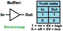
Buffers look at the high or low input state, and output the same state.
A high impedance (virtually no current flows in or out) input is important. Any current needed by the input, changes the voltage of a weak signal.
Typically used to pass along a stronger high or low signal to other circuitry, than what a weak signal can provide.
NOT:
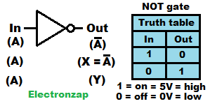
NOT logic gates look at an input signal that is either high or low, and they output the opposite.
- High: Usually close to 5V.
- Low: Usually close to 0V.
The output dot indicates that the signal is inverted. A buffer symbol is just a triangle. Buffers have the same output as the input. So, the added dot at the output indicates that it is an inverted buffer, or “NOT” a buffer.
I added in parentheses some output indications that you may see from time to time while studying NOT gate circuits.
AND
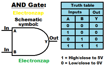
AND logic gates need all inputs to be high (1) in order for the output to be high.
If any, or all, inputs are low (0), then the output is low.
2 input AND gates are the most common, but you can get AND gate integrated circuits with more than 2 inputs.
OR
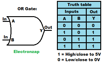
OR logic gates just need to have one input high in order for the output to be high. But, multiple, or all inputs being high, also results in the output being high. Remember that Not all logic gates have only 2 inputs.
The only way that the output is low instead of high is if all of the inputs are low.
NAND
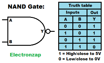
NAND gates are the inverse of the AND Gate.
The dot added to the output of the AND gate symbol indicates the the output will be the opposite of what it would be if it were simply an AND Gate.
The dot can be considered as a simplified NOT gate symbol. Indicating that the whole symbol is Not, an AND gate. Thus the name “NAND”.
- The output is high as long as any (or all) inputs are low.
- All inputs have to be high in order for the output to be low.
That’s the opposite (inverse) of the AND Gate where the output is low if any inputs are low.
NOR
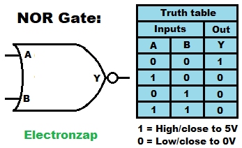
NOR gates are the opposite of OR gates. They are Not OR gates.
Any high input, results as a low output.
All inputs have to be low for the output to be high.
That’s the opposite of an OR gate, where the output is low if all inputs are low. And, the output is high if 1 or more inputs are high.
Related topics:
Schmitt Trigger:
Open Collector/Drain:
Related Pages Links:
To support this site, check out the following links:
- Become a Patron!
- Check out my YouTube videos! https://www.youtube.com/c/Electronzap/videos
- Products I used in my videos or otherwise think look like a good buy. As an Amazon associate, I earn from qualifying purchases. https://www.amazon.com/shop/electronzapdotcom
- Information on this site is not guaranteed to be accurate. Always consult the manufacturer info/datasheet of parts you use. Research the proper safety precautions for everything you do.
- Electronzap is a participant in the Amazon Services LLC Associates Program, an affiliate advertising program designed to provide a means for sites to earn advertising fees by advertising and linking to amazon.com.