Table of Contents
LEDs are diodes that are made to emit light well. They are used in a lot of circuits that aid in learning electronics, as well as being used in many practical circuits.
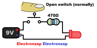
Diodes don’t limit the current that flows through them once there is enough voltage for them to conduct. LEDs commonly have a series resistor to limit current through the entire circuit, but a current source can be used instead.
The protective resistor (any resistor being used to protect the LED) needs to be high enough value to limit current to a level that is safe for the LED. The resistor value also has to be high enough that it doesn’t exceed half of it’s maximum wattage (heat dissipation) rating.
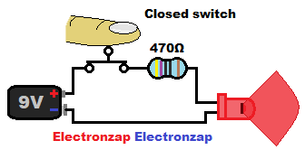
A switch is also commonly used in series with the LED and resistor to connect (closed/on) or remove (open/off) the power source from the LED.
You need to connect the LED in the proper direction to light up. The longer lead (pronounced like “leed”), called the Anode, needs to be connected towards the positive side of the power supply, while the Cathode (shorter lead), needs to be connected towards the negative side.
If the Anode has been snipped so that it is not longer than the Cathode, sometimes the rim on the Cathode side has a flat edge.
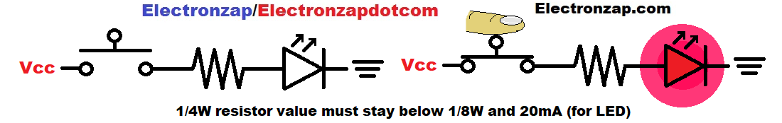
LEDs are used a lot in demonstration circuits. Usually the instructional material will show the circuit in schematic form instead of pictorial. Symbols replace components and usually suggested resistor values will be shown, but not always
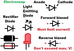
- Diode schematic symbol is an arrow with a bar at the point part of the arrow. The bar indicates the Cathode side.
- LED schematic symbols take the basic rectifier diode symbol and add outward pointing arrows to indicate that it emits something (light).
Light Emitting and other Diode type basics:
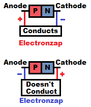
Diodes have the basic property of conducting current in one direction, while blocking current in the other direction.
- P type material makes up the Anode side of the diode.
- N type material makes up the Cathode side of the diode.
- Current flows through the diode when a relatively low voltage (forward voltage) has the Anode more positive than the Cathode.
- No current flows when the diode’s Anode is more negative than it’s Cathode (reverse voltage). However, damaging current will flow if the reverse voltage gets high enough. Some special diodes, such as zener diodes, are made to conduct current while reverse biased.
- Different diodes can have greatly different limitations. It is important to research what they are. If it has a part name/number you can likely google the part number and the word “datasheet”, and find out information about it.
P type material (Anode) versus N type material (Cathode)
Semi conductor elements, typically silicon or germanium, have atoms with 4 outermost (valence) electrons. Which doesn’t make for a good electrical conductor or insulator by itself.
- P type material is made of some of those semiconductor atoms, and adds (dopes) some atoms that have 3 valence electrons. Having 1 fewer valence electron means that the added atom will let an electron flow through when a little voltage is applied.
- N type material takes semiconductor atoms, and adds (dopes) some atoms that have 5 valence electrons. Having 1 more valence electron than the semiconductor material means that one electron can be pulled out of the atom relatively easily if a little bit of voltage is applied.
- Electrons (more negative) from the N type material can be forced through the P type material relatively easily once a low forward voltage is applied,
- Almost no electrons flow through P type material to N type material when a reverse voltage is applied
Reminder: Early scientist assumed that a positive force flows from positive to negative, because they didn’t know what exactly was going on. That gave us a conventional current system that we still use to analyze what a circuit is doing.
Now we know that electricity is electrons flowing from more negative to positive. While studying the physics of electronics, you need to keep in mind what the electrons are doing, because that’s what electricity actually is.
Good pages to check out next:
To support this site, check out the following links:
- Check out my YouTube videos! https://www.youtube.com/c/Electronzap/videos
- Products I used in my videos or otherwise think look like a good buy. As an Amazon associate, I earn from qualifying purchases.My Amazon affiliate page showing products I think look good
- Information on this site is not guaranteed to be accurate. Always consult the manufacturer info/datasheet of parts you use. Research the proper safety precautions for everything you do.
- Electronzap is a participant in the Amazon Services LLC Associates Program, an affiliate advertising program designed to provide a means for sites to earn advertising fees by advertising and linking to amazon.com.