Table of Contents
Switches are components that quickly make and break electrical connections internally. That way, you don’t have to keep manually attaching and connectors or bare wire, in order to do so.
Since switch mechanisms are usually surrounded with insulation, you don’t have to worry about them coming in contact with anything else.
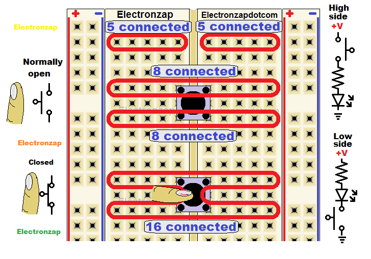
Push button switches can usually be inserted in a breadboard without much effort. Therefore they are the primary mechanical switch I focus on in my videos, because most people starting out in electronics should be building a lot of breadboard circuits.
Common connections a switch makes:
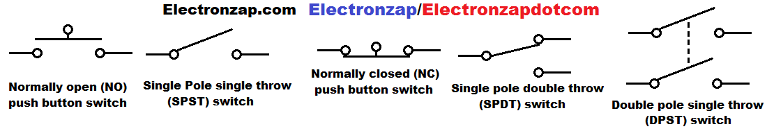
- SPST (Single Pole, Single Throw) – One terminal on each end of the switch. They are either connected to each other (on) or they are not (off)
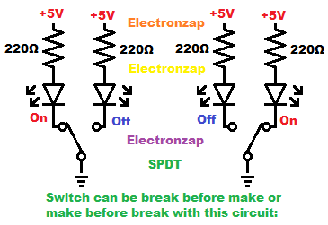
- SPDT (Single Pole, Double Throw) – One terminal, alternates being connected to 2 terminals.
- DPST (Double Pole, Single Throw)- There’s 2 terminal on one side that are completely separate from the other. Each one of those terminals has another terminals that they can connect, or disconnect from.
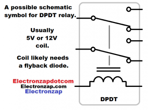
- DPDT (Double Pole, Double Throw) – There’s 2 separate terminals on one side. Both of them having 2 of their own terminals that they can switch to, for a total of 4 separate terminals on the other side of the switch.
Switches or terminals with a normal position:
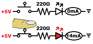
- Normally opens means that the switch holds itself open, which is off, until you force it closed, which is on.
- Normally closed means that the switch holds itself closed, which is on, until you force it open, which is off.
Many switches have a single pole, that holds itself self to one terminal (normally closed or NC), until you force it to switch the the other terminal (normally open or NC), for as long as you hold it in position.
- Make before break: While switching from one position to another, both double throw positions are connected during the middle (transition) part of the movement.
- Break before make: The switch will briefly turn off completely so that the 2 switching positions are never in contact with each other during the middle (transition) part of the switching.
The number of types of connections that switches make is almost endless. If you need a special type of switch, you simple put your requirements into the search of a place that sells switches. Such as Amazon or Ebay.
Common packages that switches come in:
- Push button:
- Toggle:
- Rocker:
- Rotary:
Digital Switches (transistor based):
To be added.
The outputs of integrated circuits (ICs) are commonly (not always) switch based. Switch based outputs usually have 1 of 2 voltages (push/pull) that they can be. Those 2 voltages are commonly close to 5V or 0V.
On and off (disconnected) IC outputs are also available. Known as open collector when an internal BJT transistor is used, or as open drain when an internal MOSFET transistor is used.
Input signals applied to input terminals determine what the output state is based on the primarily transistor based circuitry built inside the IC. The part number lets you look up the input versus output rules of those IC pins (terminals).
Electromechanical (Relay):
The switch part of a relay is mechanical. Metal parts actually move, but the control of that movement is electrical. When current pass through a coil, it create a magnetic field. That magnetic field moves the mechanical switch part of the relay.
The coil and the mechanical switch in the relay never come into physical contact with each other. The circuitry being switched can be powered by a different power source than the coil that switches it.
The coil is rated for a certain amount of voltage, which puts some current through the coil, energizing it Whereas the switch can usually switch a much higher amount of voltage and current. This makes for a cheaper option to switch high power loads with a signal, that a semiconductor based switch.
A flyback diode should be added parallel to the coil part of the relay. A reverse biased (when power is applied) diode, that is connected parallel to the coil, will give a return path for current to fade down gently while the magnetic field collapses. Otherwise, high voltage will build up to keep current briefly going through whatever is switching off the coil. Likely to damage whatever it is, especially if it is semi conductor material.
Modules are simply boards that someone has soldered a module on to, plus other components, so that all you have to do is wire a power supply to power the board (and coil), a weak signal to control the relay switch position based on the set up of the board, and the load(s) that you want to switch with it.
Latching Relay:
A latching relay (sometimes called bistable) also has 2 switching positions that 1 or more poles can switch to. But, no power is needed to stay in either position.
There should be 2 coils for a latching relay. Energizing one of them puts the switch in one position, while energizing the other one puts the switch in the other position. When coil power is removed completely, the switch stays in whatever position it is in,
Warning: A lot of sellers will advertise a relay module as being bistable or latching when it actually has a regular relay on the module, instead of a latching relay. You can give the module input a quick pulse to change the switch position, but the module keeps powering the relay to hold it in that position.
Link that returns to learn electronics page:
There’s a lot more to add to this page. I will add it later.
To support this site, check out the following links:
- Check out my YouTube videos! https://www.youtube.com/c/Electronzap/videos
- Products I used in my videos or otherwise think look like a good buy. As an Amazon associate, I earn from qualifying purchases. https://www.amazon.com/shop/electronzapdotcom
- Information on this site is not guaranteed to be accurate. Always consult the manufacturer info/datasheet of parts you use. Research the proper safety precautions for everything you do.
- Electronzap is a participant in the Amazon Services LLC Associates Program, an affiliate advertising program designed to provide a means for sites to earn advertising fees by advertising and linking to amazon.com.