Table of Contents
A series capacitor lets current flow through a BJT Base for only a short period of time. Once the capacitor is fully charged to the voltage applied to it, then the current stops completely. After that, the capacitor needs to be discharged before the current can flow again.
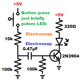
The NPN Base has a capacitor, current limiting resistor, and a push button switch are connected in series towards the positive supply.
The capacitor also has a high value resistor on each side of it that are connected to the negative supply. When the button isn’t pressed, those 2 capacitors discharge the capacitor, and then keep it discharged.
Pressing the switch gives a much lower resistance path to the positive side of the power supply. That charges the capacitor through the Base of the transistor. That small amount of Base current, allows much more current from Collector to Emitter. Since the LED and it’s protective resistor are in series with the Collector to Emitter, that current also flows through them. Therefore the LED lights up at that time.
A low value Base capacitor will quickly charge. So Base current stops pretty quickly even though the push button switch is held closed. The side of the capacitor closer to the switch will be positively charged, while the side towards ground will be negatively charged. No current will flow from Collector to Emitter, and the LED will be off. A little current will flow from the positive side of the capacitor and to ground through the resistor.
Releasing the switch disconnects the positive side of the capacitor from the positive supply, so it was discharge through the resistors on both sides of it, that head to ground.
PNP version:
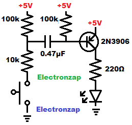
As long as you wire it for opposite polarities, you can use PNP BJTs to make the same circuits as NPN BJTs.
Closing the switch allows a small current from Emitter to Base, charging the capacitor, and then flowing through the current limiting resistor and switch to ground, until the capacitor gets charged to almost 5V.
Once the capacitor is as charged as it can get, Emitter to Base current stops. A little current will flow through the 100K resistor on the negative (closer to ground) side of the resistor, through the 10k resistor and switch to ground.
While a little PNP BJT Emitter to Base current is flowing, much more current can flow through Emitter to Collector. The LED is lit during that time. When Emitter to Base current stops, so does Emitter to Collector current, and the LED turns off.
A low value capacitor will charge more quickly, so the LED will light for a shorter period of time than a larger value capacitor.
Releasing the switch allows the capacitor to discharge through both 100k resistors on each side of the capacitor.
Good topics to check out next:
To support this site, check out the following links:
- Check out my YouTube videos! https://www.youtube.com/c/Electronzap/videos
- Products I used in my videos or otherwise think look like a good buy. As an Amazon associate, I earn from qualifying purchases. https://www.amazon.com/shop/electronzapdotcom
- Information on this site is not guaranteed to be accurate. Always consult the manufacturer info/datasheet of parts you use. Research the proper safety precautions for everything you do.
- Electronzap is a participant in the Amazon Services LLC Associates Program, an affiliate advertising program designed to provide a means for sites to earn advertising fees by advertising and linking to amazon.com.