Table of Contents
Voltage followers have an output voltage that goes up and down as the input voltage goes up and down. The NPN Bipolar Junction Transistor (BJT) Emitter will be approx. 0.6V less than the voltage at the Base when there is a load between the Emitter and ground.
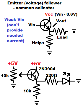
You can control the brightness of an LED by using a trimpot and an NPN BJT to set the voltage across the LED and it’s current limiting resistor.
Just enough current will flow from the signal V and through the Base to Emitter, to maintain a voltage difference of 0.6V between Base to Emitter. A little Base current results in a lot of Collector to Emitter current.
Therefore, the Collector to Emitter will conduct enough to power the Emitter to ground load at 0.6V less than the Base voltage. That larger amount of collector current, means that hardly any is needed from the signal voltage at the Base. The Base voltage should stay the same as if it isn’t powering anything in most cases.
Some loads may throw of the emitter voltage by themselves. So a parallel resistor is usually added. 10k is a common value, but it doesn’t matter very much what it’s value is. It just gives a good resistance based connection to ground.
Good topics to check out next:
To support this site, check out the following links:
- Check out my YouTube videos! https://www.youtube.com/c/Electronzap/videos
- Products I used in my videos or otherwise think look like a good buy. As an Amazon associate, I earn from qualifying purchases. https://www.amazon.com/shop/electronzapdotcom
- Information on this site is not guaranteed to be accurate. Always consult the manufacturer info/datasheet of parts you use. Research the proper safety precautions for everything you do.
- Electronzap is a participant in the Amazon Services LLC Associates Program, an affiliate advertising program designed to provide a means for sites to earn advertising fees by advertising and linking to amazon.com.