Table of Contents
Op amps have 2 inputs and 1 output. The voltage at both inputs, determines what the output voltage is.
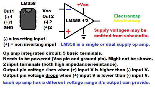
The LM358 has 2 (dual) op amps in it. Keep in mind that a lot of op amps have a different pin layout than what the LM358 has. Always consult the datasheet of the op amp you are using.
The output voltage will always be more like the non inverting input (+) than the non inverting input (-).
The output is often connected electrically to the inverting input in some way (negative feedback) in order to set the output voltage to whatever is needed to make the inverting input voltage the same as the non inverting input.
Basic Op Amp rules.
- Output voltage is always more like the voltage at the non inverting input (+), than the voltage at the inverting input (-).
- Without feed back, the op amp simply compares the voltages at the inputs and outputs one of two voltages.
- If the voltage at (+) is higher that (-), then the output is as close to the positive supply as the output can go.
- If the voltage at (+) is lower than that of (-), then the output is as close to the negative supply as the output can go.
- Non inverting comparator op amp circuits put a reference voltage at the (-) input, and a signal voltage at (+) input. A higher signal voltage than reference voltage = high output. Whereas a lower signal voltage than reference voltage = a low output.
- Inverting input comparator circuits put a reference voltage at the (+) input, and a signal voltage at the (-) input. A higher signal voltage than the reference voltage = a low output. Whereas a lower signal voltage than reference voltage = a high output.
- Negative feed back is when some or all of the output voltage is fed back to the inverting input (-). The output raises or lowers the voltage at the (-) input until it is the same as the (+) input. Then the output holds steady. That is of course, as long as there is enough supply voltage for the output to do so.
- Positive feedback is when some of the output voltage is fed back to the (+) input. Since the output V is more like (+) input than (-) input, it makes it harder for the (-) input voltage to go from lower to higher, or higher to lower, than the (+) input. That makes the output voltage more stable when the (-) voltage is changing often.
- Both positive and negative feedback is when some of the voltage is fed back to both inputs. The output makes the (-) input voltage closer to the (+) voltage until it passes it. Then the output switches states, making the (+) voltage even farther from the (-) input voltage. Now the output pulls the (-) voltage in the other direction towards the (+) voltage, until it passes it again (just in the opposite direction. Output switches voltages, repeating the process over and over for as long as power is applied.
- Op amp inputs just look at the voltage applied to them and almost no current gets through. They are high impedance. meaning that they provide a lot of resistance, probably millions to billions of Ohms or more. A small amount of current does trickle through, but it’s so low that it won’t affect the voltage of a signal unless that signal is extremely weak.
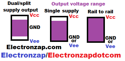
- Output types.
- Dual Supply: Intended for circuits where 0V ground is half way between a positive supply voltage, and a negative supply voltage. The output can’t get all the way to either supply rail voltage.
- Single Supply: Output voltage can get as low as the negative supply voltage, but not as high as the positive supply voltage. The negative rail voltage is 0V ground with a single power supply, so you usually need an output that can drop that low.
- Rail to Rail: Output voltage can reach either rail voltage, and or any voltage between them.
Op Amp Comparator:
The op amp is good at comparing 2 voltages in order to determine the whether the output is high (close to the positive supply voltage) or low (close to the negative supply voltage). Usually there is a specific reference voltage that you want the output voltage to switch at. And a wandering signal voltage that you want the output to switch when it crosses that reference voltage.
Non Inverting Comparator Circuit:
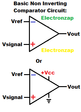
When you want the op amp output to go high whenever a signal voltage is higher than a reference voltage, versus a low output when the signal V is lower than a reference V, then a non inverting comparator should work out nicely.
The reference voltage is usually a fixed voltage from other circuitry. It connected to the inverting (-) input if you want a non inverting comparator circuit.
A signal voltage is a changing voltage that can come from many sources. The signal voltage is applied to the non inverting (+) input when you want a non inverting comparator circuit.
Inverting Comparator Circuit:
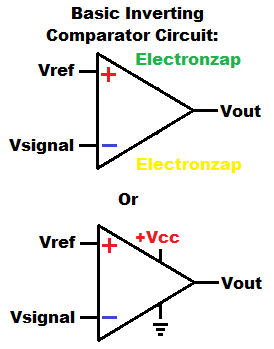
A second way to that you can wire a comparator circuit with an op amp or comparator IC, is as an inverting comparator.
- Higher signal voltage than reference voltage = Low output.
- Lower signal voltage than reference voltage = High output.
You always need to power the op amp, whether the schematic shows it or not. I included both examples in the diagram.
Voltage Follower:
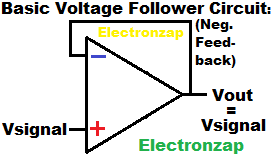
With negative feedback, the op amp output voltage will rise or fall as needed to make the (-) input the same voltage that is connected to the (+) input.
Negative feedback is when the output is connected to the inverting (-) input, so that some or all of the output voltage is given to the (-) input.
An op amp voltage follower connects the output directly to the inverting input. That means that the output will jump right to the same voltage as the (+) input, because that’s the only way that the inverting (-) input will also be at the same voltage as the (+) input.
Current source:
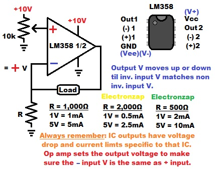
Since negative feedback makes the voltage at (-) input the same as (+), putting a resistor to from (-) to ground will set a current based on that voltage and resistance.
The output will also provide the extra voltage needed to power the load between the output and (-). As long as there is enough supply voltage for it to do so.
No current (other than miniscule leakage) goes in or out of the inputs. Therefore, all of the current from the output has to flow through the load and then the current setting resistor to ground.
A series path has equal current flowing through it. Therefore, the current through the load will be set by the voltage across the current setting resistor and the current setting resistor value as long as the output can also provide the voltage needed to pass that current through the load.
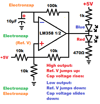
Astable Multivibrator
This page is not done yet:
I’ll be updating and editing this page a lot more in the future as I add links to related pages.
Good pages to check out next:
To support this site, check out the following links:
- Check out my YouTube videos! https://www.youtube.com/c/Electronzap/videos
- Products I used in my videos or otherwise think look like a good buy. As an Amazon associate, I earn from qualifying purchases. My Amazon affiliate page showing products I think look good
- Information on this site is not guaranteed to be accurate. Always consult the manufacturer info/datasheet of parts you use. Research the proper safety precautions for everything you do.
- Electronzap is a participant in the Amazon Services LLC Associates Program, an affiliate advertising program designed to provide a means for sites to earn advertising fees by advertising and linking to amazon.com.