Table of Contents
10,000Ω is a common value resistor for…
- Pull up or pull down resistor.
- Fixed value resistor voltage divider.
- BJT Base resistor.
One volt across a 10,000Ω (10k) resistor will result in 1V/10,000Ω = 0.0001A (0.1mA) of current flowing through it. In other words, each volt across a 10k resistor results in 0.1mA of current flowing through it. That amount of current probably won’t be able to power anything that you want powered, but it is often plenty current for providing a signal.
Pull up or down resistor:
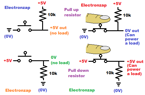
Integrated circuit input pins can often pick up voltages from the air. Usually you don’t want those stray voltages being sensed by an input.
-
- Pull up resistor is a resistor between the positive supply voltage and the input of other circuitry. As long as the input doesn’t let any current through it (other than a minuscule amount of leakage), the input will see the full positive supply voltage.
- A switch can then be added between the input and the negative supply. Closing the switch makes a direct connection to ground. Current will flow through the pull up resistor and then flow freely to the lower voltage. That extra current will not affect the voltage at the input, which just sees the lower voltage (usually considered to be 0V ground).
- Pull down resistor is a resistor between the negative supply and the input of other circuitry. it keeps the voltage at the input the same as the negative supply as long as no current (other than a miniscule amount of leakage) flows through the input.
- A switch is then added to the positive supply. When it is closed, it makes a direct connection to the positive supply so that the input sees the full positive supply. Some current will flow through the resistor from the positive supply to ground. That’s just waste current, so you should use a relatively high value pull up resistor. 10k usually works well.
- Pull up resistor is a resistor between the positive supply voltage and the input of other circuitry. As long as the input doesn’t let any current through it (other than a minuscule amount of leakage), the input will see the full positive supply voltage.
Voltage divider:
When a resistor is connected in series with other components, only a fraction of the total voltage will be across each component. Some components (semi conductors) will drop a certain voltage, but multiple resistance based components will build up a voltage across each of them based on their percentage of the total resistance.
Of course, equal value resistors in series, will divide up the total voltage equally with each other.
Half of the voltage:
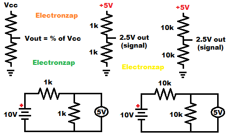
Equal value resistors make for a nice voltage divider. Two series resistors that are connected to both ends of the power source, will have half of the total supply voltage across them.
Current has to run through those resistors to build up that voltage though. So, it’s best to use relatively high value resistors in order to reduce waste power losses. Often 10k resistor work just fine to deliver a strong enough signal to most inputs, while not wasting much power.
If you are sending that divided voltage to the input of something that needs current, it will throw off the voltage based on how much current it needs. Therefore you want circuitry that doesn’t need current. Otherwise you may have to use lower value fixed resistors as a divider. Or, you can send the voltage signal to a voltage follower which will be able to provide the voltage and a significant amount of current to the input of something else.
10K based fixed value resistor voltage dividers will probably still be OK for the Bipolar Junction Transistor, as long as current needs stay minimized.
One third and two third of the voltage:
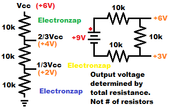
Three equal value resistors connected in series will give you both one third, and two third of the supply voltage nodes as long as you don’t draw too much current from them.
The 1/3 and 2/3 voltage nodes are the two spots where two of the resistors come together. The voltage at that point is usually in relationship to ground. Ground is usually the negative supply voltage for a single supply circuit.
Since integrated circuit (IC) inputs don’t usually pass any noticeable amount of current, 10k resistors can easily pass enough current to build up a voltage across them to build up the voltage needed to be sensed by the IC input, without wasting much power. As long as current demands are minimized, 10k fixed resistors based 1/3 and 2/3 divider will probably work for a BJT input as well.
Bipolar Junction Transistor (BJT) Base resistor:
Often you want a Bipolar Junction Transistor to saturate (turn on fully). This is especially true when you make a BJT switch circuit. That means that you want the transistor collector to conduct more than what the load needs.
- BJT Base to Emitter tends to drop 0.6V, so 4.4V will be across a 10k Base resistor when switched on in a basic BJT switch circuit.
- 4.4V/10,000Ω equals 0.00044A (0.44mA).
BJTs have gain. Gain is an approx. multiple amount of current that can flow through the Collector that is based on how much current is flowing through the Base.
- 100 gain: 0.44mA x 100 gain = 44mA of maximum current through the collector.
- 200 gain: 0.44mA x 200 gain = 88mA of maximum current through the collector.
- 300 gain: 0.44mA x 300 gain = 132 mA of maximum current through the collector.
When switching a load with a BJT, you need to make sure that the collector can pass more current than a load needs. Since small loads (such as an indicator LED) are often less than 20mA, a 10k Base resistor will work well with a BJT that has at least 100 gain. It is common for them to have 200 to 300 gain under certain circumstances. Always check the datasheet for any transistor that you are using.
Commonly seen resistor values:
Related pages:
To support this site, check out the following links:
- Check out my YouTube videos! https://www.youtube.com/c/Electronzap/videos
- Products I used in my videos or otherwise think look like a good buy. As an Amazon associate, I earn from qualifying purchases. https://www.amazon.com/shop/electronzapdotcom
- Information on this site is not guaranteed to be accurate. Always consult the manufacturer info/datasheet of parts you use. Research the proper safety precautions for everything you do.
- Electronzap is a participant in the Amazon Services LLC Associates Program, an affiliate advertising program designed to provide a means for sites to earn advertising fees by advertising and linking to amazon.com.