Table of Contents
Resistive components have a lot of uses in electronics. The more you learn about resistors, the more creative you will be in designing and modifying circuits. While studying other people’s circuits, you will usually be given a recommended 1/4W resistor value to use.
Current through a resistor.
One of the first things that people learn about using a resistor is that a resistor can limit the current through an LED.
Lighting an LED is often the first circuit that people learn about because it is a simple and useful circuit.
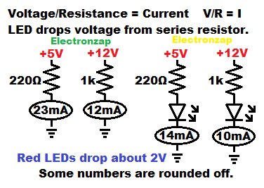
The current (I and A) will be set by the voltage (V) across the resistor divided by the resistance (R and Ω) of the resistor. Which gives us the Ohm’s law formula of I = V/R.
For example (shown in diagram), 12V/1,000Ω = 0.012A. 1,000Ω is the same as 1k, and 0.012A is the 12mA. A 1/4W will get a little hotter that desired, as explained below. But adding a series LED will drop some of the supply voltage, so that the resistor hear generation is still in the recommended range.
LED in series with a resistor:
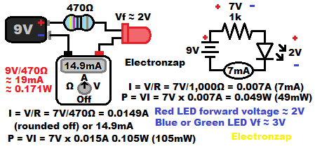
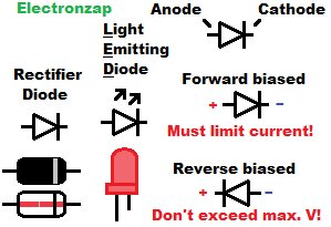
Most red LEDs absorb about 2 volts from the power supply when they are forward biased (inserted in the direction that conducts relatively easily). This is referred to as the LED’s forward voltage drop. That means there will be about 2V less across the resistor when it limits the current. LEDs don’t limit current on their own once there is more voltage than their forward voltage unless they are specially ordered to have extra resistance in them.
For example, with a 9 volt power source (mostly charged 9V battery), 470 ohm resistor and the common red indicator LED connected in series, you will have… 9 volts, with 2 of those volts dropped (absorbed) from reaching the resistor. Leaving 7 volts across the resistor, so that it sets the current through the entire series circuit at 7V/470Ω = 0.1489…A. Usually a result like that is rounded to off and convert it to milliamps. Giving us 15mA.
Combining resistors.
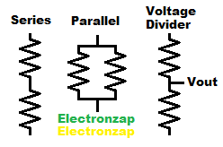
- Series resistors add up their total resistance.
- Parallel resistors all pass current without much, if any, influence from the other parallel resistors.
- Voltage dividers are formed with series resistances. Each series resistor gets a fraction of the supply voltage based on it’s percentage of the total resistance.
Wattage:
You always need to keep in mind how much heat is being generated by components and how well they can dissipate it. Resistive components generate heat based on the current being forced through them. Voltage is what forces the current through a resistance, so the voltage value across the resistor is just as important to know as the amount of current that is flowing through the resistance. Their values are actually multiplied together to get the wattage, as explained below.
- Wattage in watts (W or P for power) of a resistance is the voltage (V) across the resistance times the current in Amps (A) flowing through the resistance. P = V x I.
- Example (from above). 12V x 1,000Ω = 0.012A. Giving us 12V x 0.012A x 12V = 0.144W of power that the resistor needs to dissipate. Which is actually a little higher than desired, as explained below.
- Another example (from above). 7V/470Ω = approx. 0.015A. 0.015A x 7V = 0.105 watts of power that the resistor needs to dissipate.
- Most resistors are rated to safely dissipate a maximum of 1/4 watt (0.25W), but should be kept below 1/8W (0.125 watts). That wattage assumed that their is access to room temperature air.
- There are larger resistors (sometimes made of different material) that can dissipate more power. Giving a higher wattage rating. Still stay below half of that as much as possible.
- Whereas smaller (and sometimes made of different material) resistors will not dissipate heat as well. Giving them a lower wattage rating. Still stay below half of it’s rated value.
Related pages:
To support this site, check out the following links:
- Check out my YouTube videos! https://www.youtube.com/c/Electronzap/videos
- Products I used in my videos or otherwise think look like a good buy. As an Amazon associate, I earn from qualifying purchases.My Amazon affiliate page showing products I think look good
- Information on this site is not guaranteed to be accurate. Always consult the manufacturer info/datasheet of parts you use. Research the proper safety precautions for everything you do.
- Electronzap is a participant in the Amazon Services LLC Associates Program, an affiliate advertising program designed to provide a means for sites to earn advertising fees by advertising and linking to amazon.com.