Table of Contents
Electronics uses electricity to do something useful.
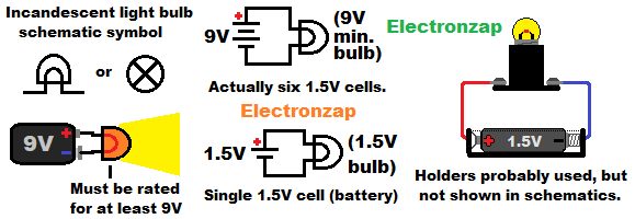
Low voltage DC light bulb circuit:
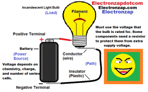
An incandescent light bulb heats up when current flows through it. With enough current, the filament heats up enough to emit light. Too much current will quickly burn out the light bulb filament.
LED circuit:
You will probably build your first LED circuits on a prototype breadboard. The LED is polarized, it only conducts current in one direct. Explained in more detail below.
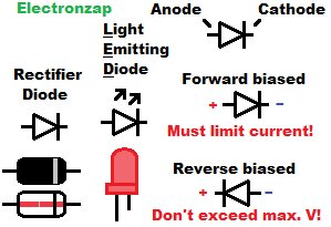
LEDs need to be inserted in the correct direction (forward biased) and have current limited (series resistor) through them, in order to light up and not burn out.
The LED Anode, which is the long lead (pronounced like leeds) wire, needs to be towards the positive side of the power supply.
Whereas the Cathode, which is the short lead wire, needs to be connected towards the negative side of the power supply.
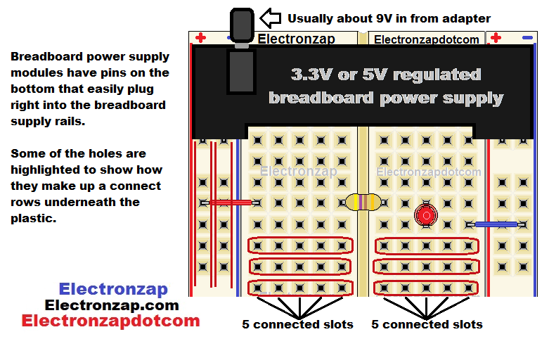
The row of breadboard holes next to the red lines are all connected to each other, but not connected to the row of holes along the red line on the other side of the board. Same goes with the holes along the blue lines. Those two areas are commonly called the power rails.
In the middle of the breadboard, there are 2 long series of 5 holes connected to each other.
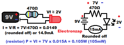
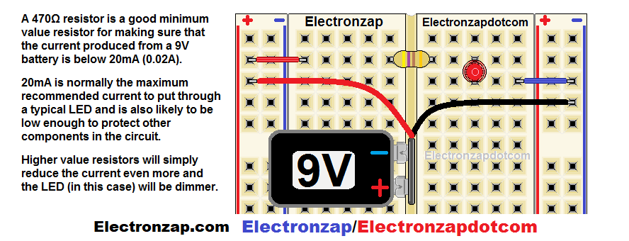
LED circuit schematic diagrams will often be square shaped with the power supply voltage (battery symbol) and resistor values given.
I also added a bubble that displays the calculated amount of current, plus the typical voltages you can expect across the LED and resistor for this circuit when the LED is red.
The series resistor sets the current through the circuit based on the voltage across it. This is known as the ohms law. formula for current. Current equals voltage divided by resistance. I = V/R.
Resistor color code:
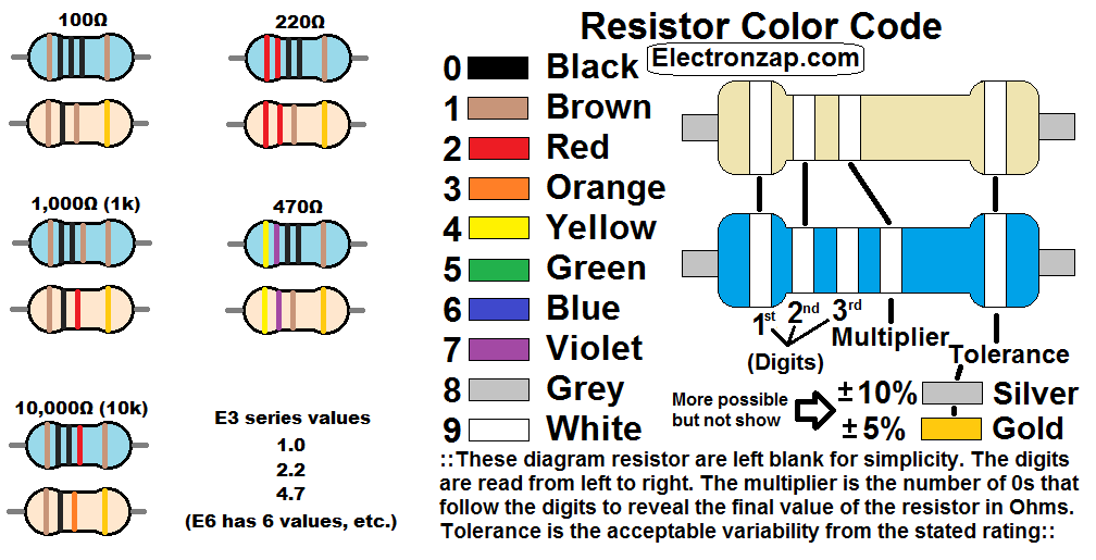
The bands (stripes) on a resistor indicate it’s resistance in ohms and also it’s tolerance. Tolerance is the percentage higher or lower (±) that the actual value of resistance might be from the stated value.
Most LEDs need current limited to no more than 20mA. And most resistor are rated for 0.25 watts (1/4W), but are recommended to stay below 0.125W (1/8W). The resistor’s resistance value limits the current through the whole (series) circuit, and determines the wattage that it generates heat from. Resistor heat generation (power) is the voltage across the resistor, times the current flowing through it. P = V x I.
Breadboard friendly push button switch.
Component kits tend to come with push button switches with 4 metal legs that will fit into a breadboards. They probably won’t fit as well as pins from other components however.
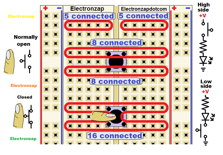
- Top 2 push button pins are usually always connected to each other. Same goes with the bottom 2 pins. It doesn’t matter which end of the switch is the top or the bottom.
- That gives 8 remaining holes for connect wires directly to the top of the switch, and 8 remaining holes for connecting wires directly to the bottom of the switch.
- I find that the pins don’t fit near as well, if at all, when you try to put the switch in sideways (pins facing up and down). The pins generally come out of the sides of the switch.
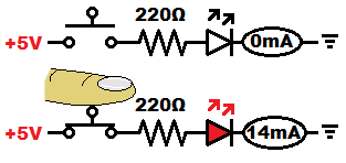
- Pushing the button closes the switch, which connects the top 2 pins of the switch to the bottom 2 pins of the switch.
Push button switch controlled LED circuit (video)
Links to next topics:
555 timer. I believe will be most fun to learn about next. Page will be created later. Or you can check out
Op amps. Can make all kinds of practical circuits especially when combined. Page will be created later. Or you can check out
To support this site, check out the following links:
- Check out my YouTube videos! https://www.youtube.com/c/Electronzap/videos
- Products I used in my videos or otherwise think look like a good buy. As an Amazon associate, I earn from qualifying purchases. My Amazon affiliate page showing products I think look good
- Information on this site is not guaranteed to be accurate. Always consult the manufacturer info/datasheet of parts you use. Research the proper safety precautions for everything you do.
- Electronzap is a participant in the Amazon Services LLC Associates Program, an affiliate advertising program designed to provide a means for sites to earn advertising fees by advertising and linking to amazon.com.