Table of Contents
Astable mode 555 timers circuits, also called multivibrator 555, have an output that constantly alternates between high and low as long as it is powered. Astable means that there is no stable state. It never stays high or low when you leave it alone.
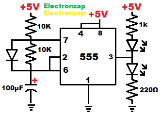
- When power is applied, pin 2 (trigger) senses that the capacitor is below 1/3 of the supply voltage, so the capacitor charges through the top resistor and diode. Without a diode, it will charge through both resistors. Each resistor in that case, adds to the charge time. While this is happening, the output is high.
- When pin 6 (threshold) senses that the capacitor has charged to 2/3 or more of the supply voltage, the output goes low (connects to ground), and pin 7 (discharge) connects to ground. That discharges the capacitor through the resistor between it and pin 7. The diode is reversed biased now, so no current flows through it. The current that flows from the positive supply (+5V in this case) through the resistor to pin 7, sinks through pin 7. It does not affect the capacitor discharge time.
- Once the capacitor voltage drops to 1/3 supply voltage or less, as sensed by pin 2, that sets the output high again and turns off pin 7. No current flows though pin 7 anymore at this time.
- The process above just keeps repeating for as long as power is applied.
- While the output is high, is it about 4V with most 555 timers when the supply is 5V. It connects to positive supply, but through transistor which drop some of the voltage. The LED between the output and ground lights up, and that is one with the voltage difference across it.
- Low output means there is about 0V at the output. The internal transistor that connect the output to ground (negative supply rail in this case) does a pretty good job of making a connection. The LED between the positive supply (+5V in this case), lights up because it is the one with the voltage difference across it.
To support this site, check out the following links:
- Check out my YouTube videos! https://www.youtube.com/c/Electronzap/videos
- Products I used in my videos or otherwise think look like a good buy. As an Amazon associate, I earn from qualifying purchases. My Amazon affiliate page showing products I think look good
- Information on this site is not guaranteed to be accurate. Always consult the manufacturer info/datasheet of parts you use. Research the proper safety precautions for everything you do.
- Electronzap is a participant in the Amazon Services LLC Associates Program, an affiliate advertising program designed to provide a means for sites to earn advertising fees by advertising and linking to amazon.com.