Table of Contents
Portable USB power banks can be used to power light loads, but most of them need to repeatedly power a higher current load for a short period of time before their auto shut off kicks in.
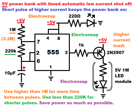
A 5V 1W LED load is able to keep my USB power bank on. But, I don’t want the 5V 1W LED on more than it has to be if I only need a much lower power load on all the time.
In Astable mode, a 555 time can easily output low pulses of short during, while there is a much longer period of time where the output is high.
While the output is high, the timing capacitor charges through 2 series resistor if no diode is added. Whereas, while the output is low, the capacitor only discharges through 1 resistor. Therefore its easy to have a much shorter period where the output is low versus high.
Video below goes live 6pm CST 6 May 2023
PNP BJT turns on (conducts fully) when it’s Base terminal is at least 0.6V less than it’s Emitter terminal, and enough Base current flows for the gain to fully power the current needs of the load. PNP BJT Base current flows when the 555 timer output is low (0V). The Base current in this circuit is being limited by a 1,000Ω (1k) resistor. That will lead to about 4.5mA of current from Emitter to Base, which is probably enough to get the PNP BJT to conduct fully from Emitter to Collector for a load demanding about 0.25A (250mA).
While the 555 output is high, it keeps the Base voltage high enough that it should keep the transistor fully off. NE555 timer outputs don’t reach the full positive supply voltage, so it my need help with a pull up resistor in some situations, to keep the PNP BJT off. But, that doesn’t seem to be an issue in this circuit.
The guidelines below are vague because the exact timing involved appears to vary considerably with different USB power banks. Just need to adjust component values until you get the timing that works well.
- Output should stay high as long as possible without the power bank auto shutting off. Higher value positive supply to pin 7 resistor increases the timing, as the resistor from pin 7 to the timing capacitor.
- Output should stay low for a long enough time to reset the auto shut off time. Resetting the auto shut off time doesn’t take very long though. So, leaving the higher current load on a lot longer than it needs to be is a big waste of power. Raising (to increase) or lowering (to decrease) the capacitor to pin 7 resistor, increases or decreases how long the output is low.
- Larger timing capacitors take longer to charge and discharge with a given resistance, while smaller value capacitors charge and discharge more quickly with a given resistance.
Checking out any item in the Amazon affiliate link below supports this site at no extra cost to you.
Good topics to check out next:
To support this site, check out the following links:
- Check out my YouTube videos! https://www.youtube.com/c/Electronzap/videos
- Products I used in my videos or otherwise think look like a good buy. As an Amazon associate, I earn from qualifying purchases. https://www.amazon.com/shop/electronzapdotcom
- Information on this site is not guaranteed to be accurate. Always consult the manufacturer info/datasheet of parts you use. Research the proper safety precautions for everything you do.
- Electronzap is a participant in the Amazon Services LLC Associates Program, an affiliate advertising program designed to provide a means for sites to earn advertising fees by advertising and linking to amazon.com.