Table of Contents
A 555 timer can be wired to output the opposite digital high or low voltage compared to the digital high or low voltage of an input signal. There is also a middle input voltage that is the hysteresis region where the output will stay in either state.
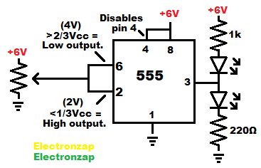
- High is considered as being close to the positive supply voltage.
- Low is considered as being close to the negative supply voltage.
- Hysteresis for a standard 555 timer circuit is when the input is between 1/3 and 2/3 of the supply voltage.
Good pages to check out next:
To support this site, check out the following links:
- Check out my YouTube videos! https://www.youtube.com/c/Electronzap/videos
- Products I used in my videos or otherwise think look like a good buy. As an Amazon associate, I earn from qualifying purchases. My Amazon affiliate page showing products I think look good
- Information on this site is not guaranteed to be accurate. Always consult the manufacturer info/datasheet of parts you use. Research the proper safety precautions for everything you do.
- Electronzap is a participant in the Amazon Services LLC Associates Program, an affiliate advertising program designed to provide a means for sites to earn advertising fees by advertising and linking to amazon.com.