Table of Contents
Photodiode lets a steady amount of current flow through it based on a steady light falling on it. That can be used to charge the timing capacitor of a 555 timer.
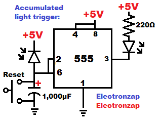
- More light will allow more current to flow through the photodiode, so the capacitor will charge to 2/3 supply voltage more quickly.
- Less light will mean that less current flows through the photodiode. It will take longer for the capacitor to charge to 2/3 supply voltage.
- Pressing the switch instantly discharges the capacitor. Pin 2 will set the output high when it senses that the capacitor is less than 1/3 supply voltage. The output stays high until pin 6 senses the capacitor has been charged to 2/3 or more supply voltage.
- Once pin 6 senses that the capacitor has charged to 2/3 supply voltage or more, it sets the output low. The output stays low until pin 2 senses that the capacitor has discharged to 1/3 supply voltage or less.
- Since the resistor protected LED load has it’s Anode towards the positive supply of 5V, and the cathode side connected to the 555 output (pin 3), the LED lights up when the 555 output goes low. The LED is off when the output is high.
Good topics to check out next:
To support this site, check out the following links:
- Become a Patron!
- Check out my YouTube videos! https://www.youtube.com/c/Electronzap/videos
- Products I used in my videos or otherwise think look like a good buy. As an Amazon associate, I earn from qualifying purchases. My Amazon affiliate page showing products I think look good
- Information on this site is not guaranteed to be accurate. Always consult the manufacturer info/datasheet of parts you use. Research the proper safety precautions for everything you do.
- Electronzap is a participant in the Amazon Services LLC Associates Program, an affiliate advertising program designed to provide a means for sites to earn advertising fees by advertising and linking to amazon.com.