Table of Contents
AND gates come with 2 or more inputs. Usually it’s 2 inputs. If any or all inputs are low, then the output is low. All inputs have to be high for the output to be high.
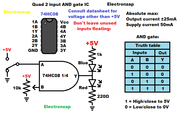
Wiring a couple LEDs to the output helps you see what the output state is.
I like using a blue LED from the positive power supply to the output. The blue LED is used to indicate that the output is low (about 0V) when the blue LED is lit up.
Heading from the output to ground, I like to use a red LED. When the output is high (close to 5V), then the red LED will light up.
A trimpot wiper terminal can output any signal voltage from one terminal of it’s resistance to the other terminal of the resistive element. The 7408 IC is not a Schmitt Trigger IC. Therefore setting the voltage about half way will give it an undetermined input, and thus possibly an undetermined output. This is just a demonstration circuit though. To get a better feel for the IC and the AND gate. Practical circuits will use a better signal source for the input.
Assorted 7400 series integrated circuit kits will likely have the 7408. For most circuits, the preferred version of 7400 series integrated circuits is the high speed CMOS (HC) version. The part number will like 74HCxx if it is a high speed CMOS version.
Links to good topics to check out next.
To support this site, check out the following links:
- Check out my YouTube videos! https://www.youtube.com/c/Electronzap/videos
- Products I used in my videos or otherwise think look like a good buy. As an Amazon associate, I earn from qualifying purchases. https://www.amazon.com/shop/electronzapdotcom
- Information on this site is not guaranteed to be accurate. Always consult the manufacturer info/datasheet of parts you use. Research the proper safety precautions for everything you do.
- Electronzap is a participant in the Amazon Services LLC Associates Program, an affiliate advertising program designed to provide a means for sites to earn advertising fees by advertising and linking to amazon.com.