Table of Contents
It’s easy to get a MOSFET (Metal Oxide Semiconductor Field Effect Transistor) to conduct fully with just a voltage. By using complimentary MOSFETs wired in a push pull configuration, you can easily alternate which one is on while the other is off. Therefore alternating whether the output is providing power from the positive or negative supply.
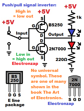
Complimentary means that the MOSFETs have opposite polarity. But otherwise have similar capabilities and limitations.
Since N and P channel enhancement mode MOSFETs connect to the supply voltage that is the opposite of the signal voltage that turns them on, the output voltage will be the opposite of the signal voltage while they are wired together as a push pull. Therefore the output is an inverted voltage of the input signal.
Good topics to check out next:
To support this site, check out the following links:
- Check out my YouTube videos! https://www.youtube.com/c/Electronzap/videos
- Products I used in my videos or otherwise think look like a good buy. As an Amazon associate, I earn from qualifying purchases. https://www.amazon.com/shop/electronzapdotcom
- Information on this site is not guaranteed to be accurate. Always consult the manufacturer info/datasheet of parts you use. Research the proper safety precautions for everything you do.
- Electronzap is a participant in the Amazon Services LLC Associates Program, an affiliate advertising program designed to provide a means for sites to earn advertising fees by advertising and linking to amazon.com.