Table of Contents
Light dependent resistors (LDRs) connected in series with a fixed value resistor, make for a nice light level dependent voltage divider. If the LDR divided voltage is sent to the input of a comparator, then the comparator will compare that voltage with another voltage at the other input.
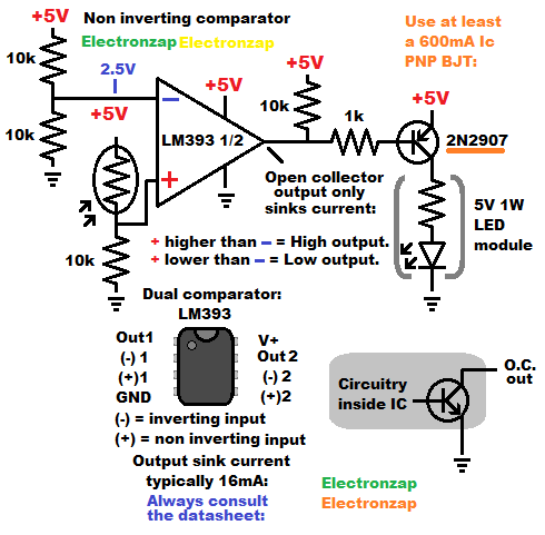
When the + input voltage is higher than the – input voltage, then the output will be high.
Whereas, when the – input voltage is higher than the +voltage, then the output will be low.
The LM393 is an open collector output comparator IC. In fact, the 8 pin dual in line package (DIP) component has 2 (dual) comparators in it. You can used either one or both.
Open collector means that it connects to ground when it is low. Whereaes the output simply turns off when it is high. Internally, there is a NPN BJT that is either on (connected to ground), or off (not conducting).
If the inverting (-) input has a fixed voltage of half of the supply voltage (2 equal value resistors divider), and you want the output low when it is dark (less light falling on the LDR), then you want the LDR on the high side of a voltage divider going to the non inverting (+) input.
If there is a pull up resistor connected to the output, then there is a positive voltage at the output when the output is high. The pull up resistor can be connected to a higher voltage (within the LM393 limit) than what is powering the LM393. They just need to share the same ground. If there’s 2 supplies, then connect their grounds directly together
With a PNP bipolar junction transistor (BJT) Base connected to the LM393 output, the PNP will be off as long as the Base voltage is as high as the voltage at the PNP BJT Emitter. The voltage at the Base can even be about 0.5V less than the Emitter voltage, but dropping down to about 0.6V less than the emitter, will start turning the transistor on.
Setting the output low, will allow current through the PNP BJT emitter to Base, through the current limiting resistor, and then to ground via the LM393 output. A small amount of current flowing through that path allow many times that amount of current to flow through the Emitter to Collector, and also through any series load headed to ground.
The 5V 1W LED passes more than 200mA of current when there is 5 volts across it. Which is what happens when the PNP BJT is turned on in this circuit. Therefore I used a 2N2907 PNP BJT, which can handle a maximum of 600mA of current. I would not use a 2N3906 because it has a max of only 200mA of current. It’s generally best to stay below half of a components maximum current as much as possible.
Checking out one of items in the affiliate link below supports this site at no extra cost to you.
Good topics to check out next:
To support this site, check out the following links:
- Check out my YouTube videos! https://www.youtube.com/c/Electronzap/videos
- Products I used in my videos or otherwise think look like a good buy. As an Amazon associate, I earn from qualifying purchases. https://www.amazon.com/shop/electronzapdotcom
- Information on this site is not guaranteed to be accurate. Always consult the manufacturer info/datasheet of parts you use. Research the proper safety precautions for everything you do.
- Electronzap is a participant in the Amazon Services LLC Associates Program, an affiliate advertising program designed to provide a means for sites to earn advertising fees by advertising and linking to amazon.com.