Table of Contents
The LM393 is a dual comparator integrated circuit (IC) component that can be used to control higher voltage loads than what is being used to power the LM393 IC. That is because the LM393 has an open collector output. Which means that output pin is simply the collector of an internally built NPN BJT, with an emitter that connects to ground when it is on. There is no conduction when it is off (high output when a pull up resistor is added).
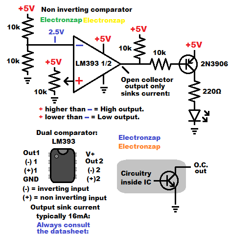
To get a high output put from an LM393, you need a pull up resistor. A resistor that connects a positive voltage to the open collector output of the LM393.
The open collector output of a LM393 can only sink current when it is low, and is limited to sinking 16ma (0.0016A) according to a datasheet.
Since current flows through the pull up resistor while the output is low (connected internally to ground), a high value resistor is generally used.
Being a comparator, the output is low when the non inverting input (+) has a lower voltage attached to it, than the voltage at the inverting (-) input.
Whereas the LM393 comparator has a high output when the + input has a higher voltage applied to it than the – input.
Checking out one of items in the affiliate link below supports this site at no extra cost to you.
In the demonstration circuit above, an LM393 is used to switch a PNP BJT on and off. The PNP BJT is being used to power an LED.
- 5V holds a PNP BJT off when there’s 5V at the emitter. The LM393 output needs to be off (high) during that time, so no current is needed through the pull up resistor. Voltage transfers through resistors when no current can flow through the resistors.
- 0V at the LM393 OC output results in a small amount of current flowing through the pull up resistor since it is a 10k resistor. That mean’s that the voltage at the output drops to 0V. A small amount of current also flows through the PNP BJT emitter to base, through the 10k current limiting resistor, and then to ground through the output. That small amount of PNP BJT Emitter to Base current, allows a lot more Emitter to Collector current. Much more than the LED and it’s protective resistor needs. Therefore the LED turns on, and the LED’s protective resistor limits the current through the LED and the PNP BJT Emitter to Collector.
To be added:
- Night light circuit: LM393 responds to a light dependent resistor voltage divider. External light level determines whether a PNP BJT switches a fairly bright 5V 1W led component.
- Higher voltage load than what is being used to power the LM393 IC.
Good topics to check out next:
To support this site, check out the following links:
- Check out my YouTube videos! https://www.youtube.com/c/Electronzap/videos
- Products I used in my videos or otherwise think look like a good buy. As an Amazon associate, I earn from qualifying purchases. https://www.amazon.com/shop/electronzapdotcom
- Information on this site is not guaranteed to be accurate. Always consult the manufacturer info/datasheet of parts you use. Research the proper safety precautions for everything you do.
- Electronzap is a participant in the Amazon Services LLC Associates Program, an affiliate advertising program designed to provide a means for sites to earn advertising fees by advertising and linking to amazon.com.