Table of Contents
The Op Amp can continuously alternate (Astable) it’s output high and low by sending the output voltage to a divided voltage at the non inverting (+) input (positive feedback), and also a limited amount of output current to a capacitor at the inverting input (-) (negative feedback).
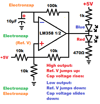
- Output is either High (close to positive supply voltage), or Low, (close to negative supply voltage).
- High output, pulls up the voltage at the non inverting (+) input and charges (raises the voltage) of the capacitor at the inverting (-) input.
- Low output pulls down the voltage at the + input and discharges (lowers the voltage of) the capacitor at the (-) input.
- Output will be high as long as the capacitor voltage is lower than (+) voltage, which is the reference voltage. As soon as the capacitor voltage rises above the reference voltage, the output flips low.
- Output will be low as long as the capacitor voltage is higher than the reference voltage. As soon as the capacitor discharges to a voltage lower than the reference voltage, the output will go high.
- Blue LED load with protective resistor between the positive supply and the output will light up when the output is low. This will likely throw off the op amp output voltage a bit as many Op Amps are not great at powering loads.
- Red LED load with protective resistor between the output and the negative supply will light up when the output is high. This will likely throw off the op amp output voltage a bit as many Op Amps are not great at powering loads.
- The value of the negative feedback resistor and capacitor primarily sets the timing.
- The + input equal value resistors voltage divider (the two 10k resistors going to opposite supply voltages) tries to set the + input to 1/2 of the supply voltage. Which is 2.5V in this case, since the supply voltage is 5V. But, the positive feed back resistor shifts it a bit in either direction. The lower the value of the positive feedback resistor, the close it will shift the + input voltage towards the output voltage. The wider that voltage range (called hysteresis) is, the longer it will take the capacitor to charge and discharge between them.
- I used the LM358 for my demonstration video. It is a single supply Op Amp. A dual supply Op Amp has a middle voltage that is the 0V ground, which is between both a positive and negative supply voltage. With a dual supply power source, a single resistor can go from the + input to the dual supply ground, while the power pins for the Op Amp are plugged into the positive and negative supply voltages. Ground is a midway voltage for a dual supply, instead of being the most negative voltage, which is the case for a single supply. The LM358 will also work with a dual supply power source, but a dual supply Op Amp may not work well with a single supply power source.
Demonstration Video:
Video below goes live at 6AM CST 21 May 2023
Always remember that the Op Amp output voltage wants to be more like the + input voltage than the – input voltage. If those voltage aren’t equal, then the output will be whichever supply voltage that the + input is closer to than the – input. As close to that voltage as it can reach anyways. Only rail to rail output op amps can output the full range of the supply other than a tiny bit of voltage loss at no current.
Good pages to check out next:
To support this site, check out the following links:
- Check out my YouTube videos! https://www.youtube.com/c/Electronzap/videos
- Products I used in my videos or otherwise think look like a good buy. As an Amazon associate, I earn from qualifying purchases. https://www.amazon.com/shop/electronzapdotcom
- Information on this site is not guaranteed to be accurate. Always consult the manufacturer info/datasheet of parts you use. Research the proper safety precautions for everything you do.
- Electronzap is a participant in the Amazon Services LLC Associates Program, an affiliate advertising program designed to provide a means for sites to earn advertising fees by advertising and linking to amazon.com.