Press the buttons below to close the switch (turn on) and open the switch (turn off) of the circuit drawing.
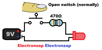
- LED is off while the switch (and thus the circuit) are open.
- Pressing the switch closes the switch, and thus the circuit. Which turns on the LED .
Becoming a Patreon member will help me reduce ads and make more content!
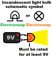
Simple circuit introduction: Incandescent Lightbulb.
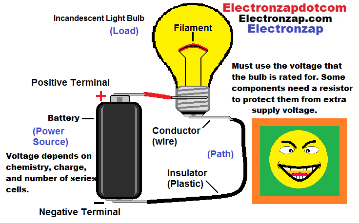
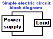
- Power supply: Provides voltage and current.
- Batteries use chemical energy, whereas generators move wires past magnets.
- Generators mostly provide high voltage alternating current (AC). Which is mostly used to power houses and businesses.
- Power supplies plug into that generated AC, and convert it into the direct current (DC) typically used in electronics.
- Inverters take a DC source, such as batteries, and converts it into (usually higher voltage) AC.
- Load: Usually does something useful (emit light, turn a motor, creates sound, etc.) with the power (voltage and current) provided by the power supply. The load also always creates waste heat.
- Efficient loads produce little waste heat compared to how much useful power is provided.
- Conductors: Transfer voltage and allows current to move easily.
- Insulators: Block almost all voltage and current.
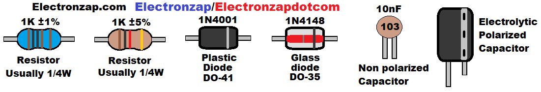
Physical appearance of commonly used through hole (wires sticking out) components:
Common Schematic symbols for components:
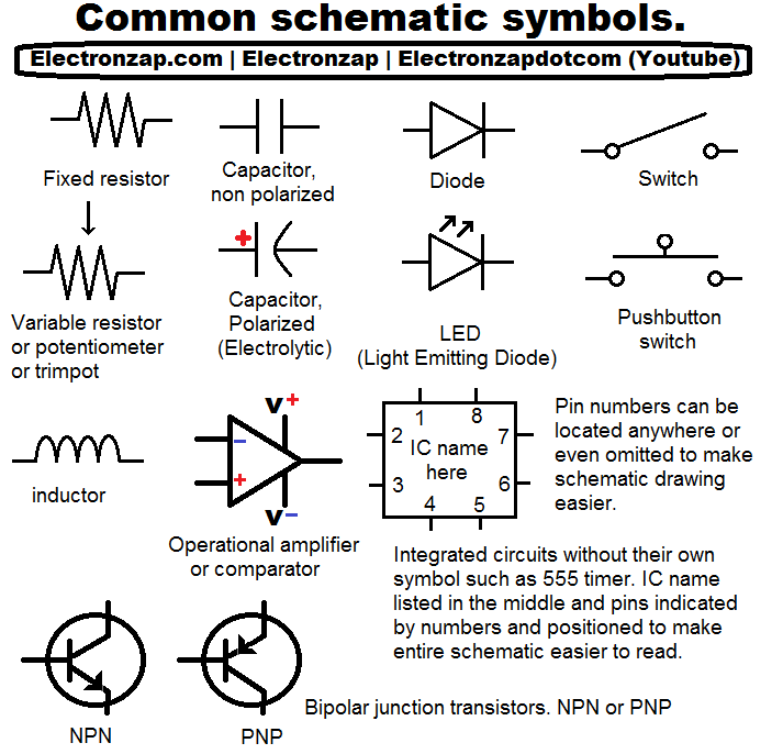
Symbols are used in schematic diagrams to represent physical components.
You simply connect the terminals where the lines connect.
It is still important to learn how the components work in order to modify and trouble shoot the physical circuits that you build.
You will often have to substitute components you see on the schematic. You may not have the exact value component(s) shown, or you may need to make some changes to the circuit to obtain what you want.
Keep in mind that most practical electrical and electronics projects these days involves buying prebuilt, or easy to wire, systems. You can find tutorials where you can start using them right away by doing a Google/YouTube search of the topic(s). some examples are…
Click here to view/hide the list of topics.
- Solar panels.
- Battery banks.
- Inverters
- Wires/Connectors.
- Arduino: A kind of user programmable mini computer made to connect directly to circuits/modules.
- Circuit modules.
- Boost converter.
- Buck converter.
- Relay.
- Sensor.
- Audio
- Speakers.
- Amplifiers.
Learning basic electronics will help you make better choices in your electronics purchases, and sooner or later, you will probably want to build some things from scratch.
Basic Circuit: LED protected with a resistor.
You need to be familiar with basic circuits before you will be able to understand more complex circuits. Most people that are learning electronics build temporary circuits on electronics prototype breadboards. They have rows of slots that electrically connect wires and pins to each other.
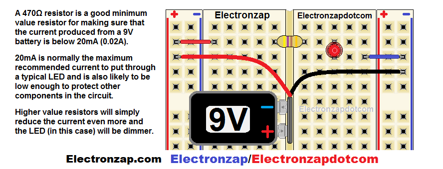
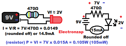
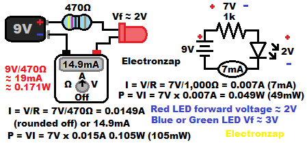
Above is a drawing of an LED (Light Emitting Diode) protected by a series 470 ohm current limiting resistor. It is powered by a 9V battery, which provides the power (voltage and current).
- Resistor protects all of the components of this circuit from overheating by limiting current.
- LED and resistor are powered by a 9V battery.
- Resistor power is converted into waste heat.
- LED power is mostly converted into light, but also some waste heat. In order to light up, the longer LED wire lead (pronounced like leeds) needs to be closer to the positive side of the battery, while the shorter lead needs to be connected towards the negative side of the battery. That is called wiring the LED forward biased (FB). Diodes are basically one way valves for electricity.
- The components are all temporarily connected together on a prototype breadboard in the drawing. The 9V battery snap, which connects the battery terminals to stranded wires (a bunch of tiny wires). I twist the stranded wires together so that they will plug into the breadboard better.
You will rarely see a drawing of a breadboard circuit.
There’s a chance that you will see a pictorial like the one shown here. But, you will most likely see a schematic diagram of the circuit similar to the one to the right of the pictorial.
I added some additional information to this schematic diagram:
- Supply/Battery voltage (usually shown on schematics).
- Resistance value (usually shown on schematics).
- Approximate voltages across the resistor and the LED. There is usually 2 volts across a red LED, and the rest of the supply voltage across the series resistor. (Not usually shown on schematics).
- Circuit current, which is the same through all series components and connectors. May indicate an actual ammeter/multimeter measuring current at that point. (Not usually shown on schematics, and not usually something you measure).
Electrical properties to be aware of:
- Voltage: Electric potential. Batteries and electrical outlets have voltage that you can use to power a suitable load.
- Current: Moving charges/electrons. Pushed by the voltage of a power source, and limited by a load.
- Resistance: Opposition to current.
- Semi conduction: Components that conduct more or less depending on the exact voltages and/or currents involved, and by which direction the voltage is applied (polarity).
- Wattage: Work done, such as the heat that is generated. Calculating wattage (P) is done by taking the voltage (V) across a component times the current (I) through the component. P = V x I
- Power loss and efficiency: Usually referred to when converting power (Input versus output). But also refers to how much of the total power provided is consumed as waste heat.
Primary goals when building/designing a circuit:
Whenever studying a new circuit, try to make sure you understand how every part of the circuit contributes to these 2 goals.
- Don’t let any part of the circuit overheat (wattage).
- Use components that provide the desired outcome.
Visualizing electric current:
Current runs equally through all series (connected end to end) components, including the power supply. The current is pushed by the power supply voltage, and it’s rate of flow is limited by the components.
Never connect the power supply terminals directly to each other (short circuit) with metal or other low resistance material.
You can’t see electric current, you can only detect, or measure, it’s effects.
It helps to visualize current in a way similar to what is drawn below.
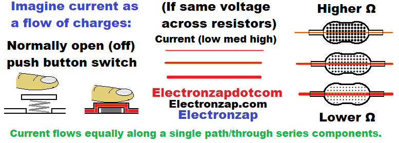
- Mechanical switches are made so that they don’t conduct current while they are open/off (no metal on metal contact). Whereas they conduct close to freely while they are closed/on.
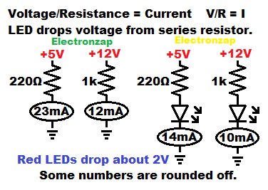
- Resistors provide a specific resistance (opposition to current flow) to a circuit. They come in a lot of different values.
- When the same voltage is applied, lower value resistors conduct more current than higher value resistors do.
- Lower value resistors also produce more heat with the same voltage across them because of the higher current. Preventing too much heat in any circuit is always the top priority in electronics.
Power (heat production for components) is the voltage across a component, times the current through the component. P = VI
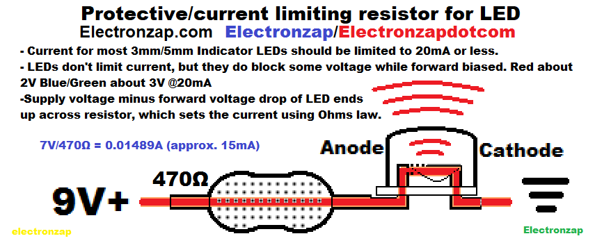
Current only flows through a diode (such as an LED), when the anode is more positive than the cathode by a small voltage. In the drawing above, the 0V ground reference point symbol is the 3 different length horizontal lines next to the LED (light emitting diode) cathode. Usually it is just referred to as the ground symbol. That usually indicates the negative side of a battery or other single supply power source when using DC power.
9V+ (or +9V) is being used to represent the positive terminal of a 9V battery. There’s a 9V difference between +9V and ground (0V).
Push button switch on a breadboard:
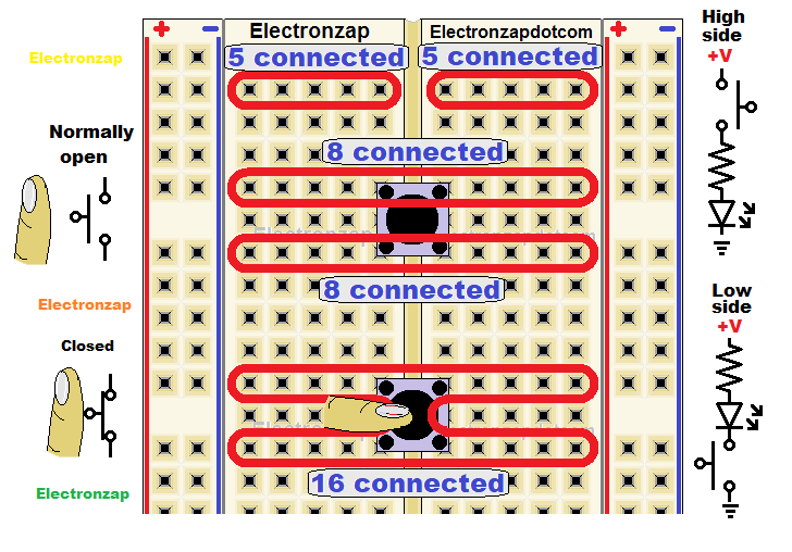
- Common push button switches usually fit into breadboards reasonable well. A new breadboard will likely pop out push button switches once in a while. Wire leads may not fit into the slots as well after a pushbutton had been inserted into them previously, so I mostly devote those slots to pushbuttons.
- The 2 pins at the top of the push button switch connect the 2 breadboard rows that they are plugged into. The bottom 2 rows are also connected by the 2 lower pushbutton switch pins.
- Pressing the switch button until it clicks to turn it on, electrically connects the top 2 rows to the bottom 2 rows electrically. This is the case for normally open (NO) switches, which are more common. There are also normally closed (NC) switches, but you will probably have to put a lot more effort into finding them.
- High side switching is when the switch is on the more positive side of the circuit than the load. That’s the most common position for the switch.
- Low side switching is when the switch is on the more negative side of the circuit than the load. That is the less common position, but it is still an OK place to put the switch if it is better for the circuit. Some people may be annoyed that you put a switch on the low side, especially if they don’t understand why. For example, some transistors (NPN BJTs) have to be on the low side when wired as a switch.
Breadboard power supply basics:
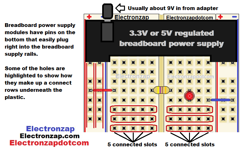
Breadboard power supplies have pins that plug into the breadboard supply rails. The supply has to be powered at the barrel jack. Typically with a 9V AC to DC wall adapter.
Breadboards are used to quickly build, modify and study test circuits. Breadboards have a lot of slots for wires to be inserted into. Each row of slots is connected together electrically within the board.
On both sides of the groove running down the middle, there are a bunch of rows of 5 slots across that are connected to each other. Then there’s 2 rows of slots connected all the way from top to bottom on both sides. Those slots are intended for connecting the power supply to.
I have however seen videos where people were using a board where the supply rails were separated half way. So you may run into one like that.
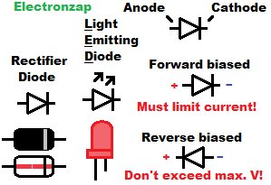
Diode/LED polarity
- LED must be inserted in the right direction to light up (forward biased). That is when the Anode (longer lead) is more positive, and the Cathode (shorter lead) is more negative. Leads (pronounced as “leeds”) are the metal wires coming out of any through hole component. The leads are what go through the holes of a circuit board, and then are soldered on the other side for permanent circuits. Many LEDs also have a flat edge on the cathode side.
- Rectifier diodes are used when you actually want to prevent current from flowing in the wrong direction. Compared to LEDs, they conduct more easily (lower forward voltage) while forward biased, and can handle more current than LEDs. They also have a much higher reverse breakdown voltage than LEDs. Which means that they can block a lot more voltage while reverse biased.
Rectifier and other types of diodes have a band painted on the cathode side of the component.
Minimum resistance to protect an LED from common low voltages
Until you are comfortable with calculating circuit current and resistor wattage, here are some good minimum value resistors to use to protect an LED from a given voltage. This assumes that you are using 1/4W (quarter watt) resistors, which are the most commonly available wattage value.
-
-
- 5V – 220Ω (two hundred twenty ohms)
- 9V – 470Ω (four hundred seventy ohms)
- 12V – 1000Ω (1k) (one thousand ohms/one kilohms)
-
Notice how I suggest to use about 4 times the resistance to protect an LED from a little more than twice the voltage.
Resistors get 4 times as hot when the voltage across them doubles. That is because you need 2 times the voltage across a resistor t get 2 times the current through the resistor. The voltage and current are multiplied together for wattage. Thus giving us 4X the wattage when voltage (and therefore current) is doubled.
Notice how there is less current through the circuit when an LED is in series with a resistor than a resistor alone. That is because the LED drops some of the supply voltage (usually 2-3V) from the resistor. The resistor sets the current based on the supply voltage minus the LED voltage drop.
Ohms law:
The relationship between voltage and current of a resistive component is known as Ohms law. The 3 main formulas for doing Ohms law calculations are
- I = V/R
- R= V/I
- V = IR
Examples:
-
-
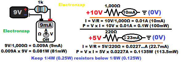
- 5V/220Ω = 0.022727…A (which is rounded off to 23mA)
- 12V/1000Ω (same as 1k) = 0.012A (same as 12mA)
-
Current through a resistor and a series LED that drops 2V:
-
-
- 3V/220 = 0.013636… (14mA)
- 10V/1,000Ω = 0.01A (10mA)
-
Protective resistor must have high enough resistance to limit current below 20mA for most indicator LEDs. At higher voltages, current will need to stay well below 0.02A (20mA) to prevent 1/4W resistors from overheating.
Using Ohms law for calculating current and multimeter measurements learning electronics lesson 0003
Most resistors are rated to dissipate a maximum of 1/4W (0.25W) of power. However, it is still recommended to keep them below 1/8W (0.125W). Other wattage resistors are fairly easy to buy. They should also be kept below half of whatever their maximum wattage rating is.
To calculate wattage, take the voltage (in volts) across a component, and multiply it by the current through it (in amps). W = V x I
Wattage and power calculations for resistive components learning electronics lesson 0004
Battery basics:
Batteries are a cheaper, and more portable, voltage source than a plug in power supply. But they need to be replaced often, or recharged if they are rechargeable.
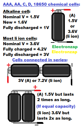
A cell contains the chemistry needed to provide the voltage and current. The nominal voltage will depend on the chemistry involved.
Nominal voltage is close to the average voltage that you can expect from a cell when it goes from fully charged (highest voltage possible) to fully discharged (lowest practical voltage).
-
-
- Alkaline cells have a nominal voltage of 1.5V. The actual voltage starts at approximately 1.6V while brand new, and ends somewhere close to 1V when fully discharged. Alkaline isn’t usually rechargeable.
- Lithium ion (li ion) cells usually have a nominal voltage of 3.6V. Being 4.2V when fully charged and 3V when fully discharged. Always stay within that voltage range, and never exceed it’s maximum current in order to prevent damage.
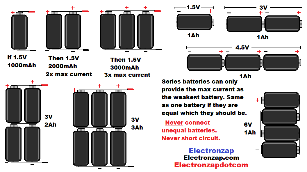
- Series cells: Cells must be at the same voltage and have the same capacity (mAh). Connecting cells end to end (positive of one cell to negative of another cell) adds up the voltage of each cell when measured from the 2 far ends.
- Parallel cells: Cells must be at the same voltage when connected. Connecting the positive side of any number of cells together, and connecting all their negative side together adds up how much total current can be provided to a load. Make sure the batteries are at the same voltage (no more than about 0.1V difference) before connecting in parallel. Once in parallel, they will stay at the same voltage.
-
Battery holders are easy to purchase. They connect the cells in series or parallel for you when you insert them in the proper direction;
A 9V alkaline battery has six 1.5V cells connected in series contained in one package. 6 x 1.5v = 9V.
BEWARE that a”9 volt” lithium ion rechargeable batteries can only be charged to 8.4V. That is because they are made up of two series 3.6V cells, which are a maximum of 4.2V each when fully charged. I prefer to call them almost 9V batteries. 4.2V + 4.2V = 8.4V
Always use a proper battery charger for the chemistry involved, unless you have learned how to charge that chemistry safely.
Make sure to subscribe and ring the bell! from r/ElectronicsStudy
To support this site, check out the following links:
- Become a Patron!
- Check out my YouTube videos! https://www.youtube.com/c/Electronzap/videos
- Products I used in my videos or otherwise think look like a good buy. As an Amazon associate, I earn from qualifying purchases. My Amazon affiliate page showing products I think look good
- Information on this site is not guaranteed to be accurate. Always consult the manufacturer info/datasheet of parts you use. Research the proper safety precautions for everything you do.
- Electronzap is a participant in the Amazon Services LLC Associates Program, an affiliate advertising program designed to provide a means for sites to earn advertising fees by advertising and linking to amazon.com.