Table of Contents
Even in DC powered circuits, the current flows back and forth through a capacitor every time it charges and discharges. That makes it easy to occasionally put it in series with the power supply in order to add up their voltages.
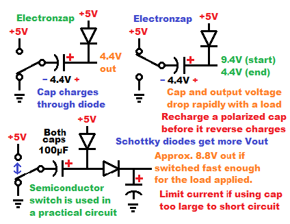
For this voltage doubler circuit, one side of the capacitor (positive side if it is polarized) has a diode coming from the positive supply. That diode lets the capacitor charge when the other side of the capacitor is connected to the negative side of the power supply. With no other components, the capacitor charges instantly to the supply voltage minus the forward voltage of the diode.
If the negative side of the capacitor is now connected to the positive supply, then the power supply and charged capacitor are connected in series. Therefore, their voltages add up. If using a 5V power supply, and 0.6V forward voltage diode, there will be a total of approx. 9.4V at the positive side of the power supply. That is why you need a diode between the positive supply and the positive side of the capacitor. Current will flow back to the positive supply from the initially higher voltage positive side of the capacitor.
Storing or using that higher voltage
The extra voltage that you get from the capacitor in series with the power supply can be pumped into another capacitor for storage if you use another diode to keep that current from returning to the original capacitor.
It takes multiple alternating high and low power switches to fully charge the second capacitor. Especially if it is larger value than the original capacitor. The storage capacitor can be as high of a value as you want, but the doubling capacitor is often short circuited for a brief period, so you want to keep the total current flow with each switching to a minimum. 1,000µF is the largest value I would try using.
When it comes to how much power you can get out of the circuit, how often you switch back and forth from high and low is more important than what the capacitor size is. Usually a load is connected in parallel to the storage capacitor. The capacitor’s stored charged is ultimately what powers the load. Toping it off faster than how fast it is being discharged through is the only way to hold the voltage close to the doubled (minus diode drops) voltage.
Using 2 silicon rectifier diodes, you can expect to lose approx. 0.6V with each of them, for a total loss of about 1.2V to the storage capacitor and load. With a 5V supply, you can expect a maximum of about 8.8V out.
Good topics to check out next:
To support this site, check out the following links:
- Check out my YouTube videos! https://www.youtube.com/c/Electronzap/videos
- Products I used in my videos or otherwise think look like a good buy. As an Amazon associate, I earn from qualifying purchases. https://www.amazon.com/shop/electronzapdotcom
- Information on this site is not guaranteed to be accurate. Always consult the manufacturer info/datasheet of parts you use. Research the proper safety precautions for everything you do.
- Electronzap is a participant in the Amazon Services LLC Associates Program, an affiliate advertising program designed to provide a means for sites to earn advertising fees by advertising and linking to amazon.com.