Table of Contents
SG90 servo position relies on the width of pulses that are spaces about 20ms (twenty milliseconds) apart.
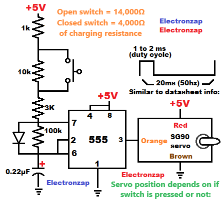
According to the SG90 datasheet I found, each pulse should be about 1 to 2 ms.
The 555 timer can easily make pulses of various lengths and that are spaced a certain amount apart.
While the capacitor connected to pins 6 and 2 is charging up to 2/3 of the supply voltage, the 555 timer output is high.
Whereas while the capacitor connected to pins 2 and 6 is discharging, the output is low.
I didn’t measure the 555 timer output, but with the timing capacitor and timing resistors in the schematic, I was able to get the SG90 servo to be either in one position, or to move into a little more than 180 degrees into a different position. The arm connected to the servo can easily be removed, so that you can set it into one of the positions that you want.
Good pages to check out next:
To support this site, check out the following links:
Become a Patron! I currently share my new diagrams with patron supporters and will also share them with anyone that joins my YouTube channel through the following link.
Become a member of my YouTube channel!
- Check out my YouTube videos! https://www.youtube.com/c/Electronzap/videos
- Products I used in my videos or otherwise think look like a good buy. As an Amazon associate, I earn from qualifying purchases. My Amazon affiliate page showing products I think look good
- Information on this site is not guaranteed to be accurate. Always consult the manufacturer info/datasheet of parts you use. Research the proper safety precautions for everything you do.
- Electronzap is a participant in the Amazon Services LLC Associates Program, an affiliate advertising program designed to provide a means for sites to earn advertising fees by advertising and linking to amazon.com.