Table of Contents
Typically 555 timer integrated circuit pin 5 (control) gets a low value capacitor (often 0.01µF) connecting it to ground. This can help the internal voltage divider maintain 2/3 of the supply voltage. The main thing to remember is that pin 5 is a direct connection to the 2/3 (high) side of the internal voltage divider.
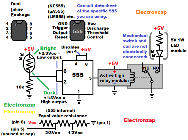
Instead of a capacitor, you can leave pin 5 floating with probably no noticeable effect, or you can add resistance between pin 5 and one or both (divider) supply voltages. Adding resistance will raise or lower the voltage of the high side voltage divider in the 555 timer. This of course will also move the voltage at the low side divider, which will always be half of what the high side voltage is.
The most obvious impact of changing the high side voltage divider (and the low side by half as much) is that you can adjust the 555 timer astable circuit duty cycle by quite a bit.
Good topics to check out next:
To support this site, check out the following links:
- Become a Patron!
- Check out my YouTube videos! https://www.youtube.com/c/Electronzap/videos
- Products I used in my videos or otherwise think look like a good buy. As an Amazon associate, I earn from qualifying purchases. My Amazon affiliate page showing products I think look good
- Information on this site is not guaranteed to be accurate. Always consult the manufacturer info/datasheet of parts you use. Research the proper safety precautions for everything you do.
- Electronzap is a participant in the Amazon Services LLC Associates Program, an affiliate advertising program designed to provide a means for sites to earn advertising fees by advertising and linking to amazon.com.