Table of Contents
Schematic diagrams are the primary way that electronic and electric circuits are explained.
Introduction:

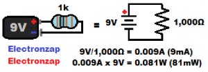
A battery and resistor symbol is commonly shown in beginner electronics. A circuit needs at least a power source (battery) and a load (resistive component).
Note how the circuit the resistor needs to be connected to both sides of the power source to receive power. Both the positive and negative terminals need to be connected to opposite ends of the resistor.
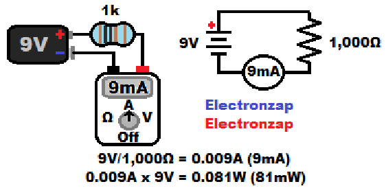
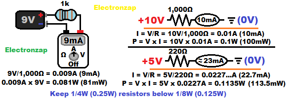
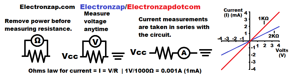
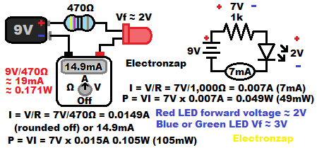
Current through a resistance is the voltage (V) across it divided by it’s resistance in ohms. That gives you the current (I) in amps. Ohms law formula…. I=V/R.
You can measure the current with a meter, as shown. You need to open the circuit by disconnecting the resistor from the battery, and then bridge the gap with the meter. The meter needs to be set to measure more current than you can expect t0 measure, otherwise the meter might be damaged.
If you see a bubble added to a schematics that indicates calculated current flow, you probably don’t need to actually measure the current. It will likely just be the schematic drawer’s way of letting you know how much current will flow through that circuit. 9V/1,000Ω = 0.009A. Which is the same as 9 milliamps (9mA).
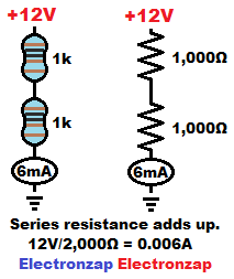
Resistive components that are connected in series (end to end) simply add up how much resistance they provide.
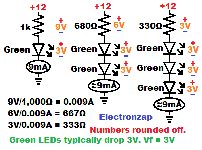
12 volts divided by 2,000 ohms of resistance (due to two 1,000Ω resistors being connected in series) results in 12V/2,000Ω of resistance = 0.006A (or 6mA) of current to flow through the circuit. You can add resistors in series as needed to get a desired voltage. They also split up the power (waste heat) dissipation as the current has to flow through all of them.
Note how the positive power source is indicated by a number (+12V in this case, because it is a 12V power source). whereas the negative terminals is indicated with a ground symbol. Ground is normally considered to be 0 volts. +12V is 12 volts higher than 0V. That gives a 12V difference between those 2 points.
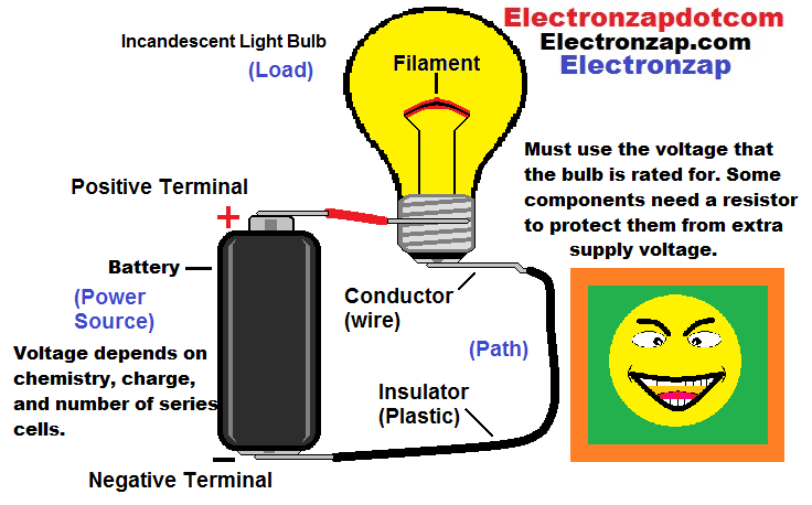
Pictorials help show how physical components can be connected with metal on metal contact for those new to electronics. But Schematics are more practical than pictorials once you understand how to read schematics.
There is also no way that schematics show how to make the physical connections of components. They just show where there are connections that need to be made.
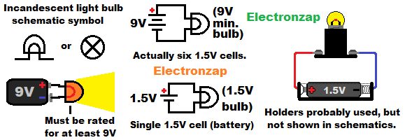
Light bulbs need to be rated for at least as much voltage as what will be given to them. The required voltage and current (wattage) rating of components will rarely be noted on the schematic. Those topics are covered in detail while studying basic electronics material.
Block diagrams:
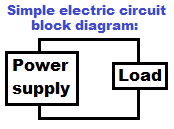
Sometimes you will see block diagrams.
They are not circuit diagrams. They simply show how different circuit fragments can be connected together to be made into a larger circuits.
The components that you use to put together the circuit depends on what you have available, and the needs of each circuit fragment.
Voltage/Power Source:
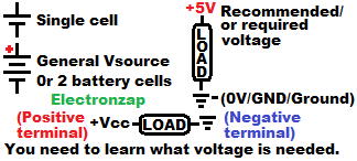
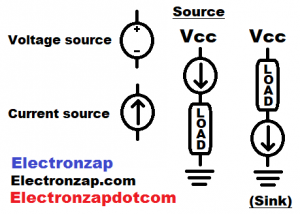
Voltage sources are shown a number of ways in schematics. The diagram shows a few ways that are commonly used.
Note: Vsource is short for voltage source.
-
- Symbol showing the total number of battery cells when battery/cell chemistry is known. For example, you might see 4 cells stacked together to indicate a 6V battery made with four 1.5V alkaline cells. 4 x 1.5V = 6V. Not an example that is shown in the diagram.
- 2 cell symbol: Two cells stacked in top of each other. More commonly used as a general battery symbol instead of the actual number of cells is not shown. You combine batteries in series as needed to get the voltage shown.
- The positive, and sometimes negative, voltage in relationship to ground. 5V (or +5V) is common these days.
- Ground is usually considered to be zero volts. It typically has a symbol made up of 3 lines of different lengths. Longest and on, and shorted on the bottom.
- The Vcc symbol comes from bipolar junction transistor circuits. It is however sometimes seen in other circuits. Vcc usually indicates the positive supply voltage of a circuit when an exact voltage isn’t given. There may also be a plus symbol added to Vcc, giving us +Vcc.
No values given basic switch controlled LED circuit:
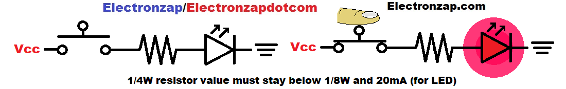
The switch control LED circuit schematic above doesn’t have a specific supply voltage given. You have to determine the supply voltage, and what resistance is needed to protect the entire circuit. Important topics to understand when starting to learning electronics.
When I made the diagram above, I mostly wanted to illustrate the push button switch.
You need to make sure that the resistor limits current enough to protect the LED. And, that the resistor doesn’t over heat. Depending on the supply voltage, you may need to combine 1/4W resistor, or use a higher wattage resistor. Things to keep in mind as you look at similar circuits.
Dual/Split supply.
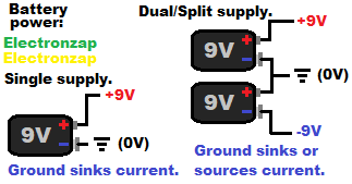
Some circuits need both a positive and a negative voltage in relationship to ground. It is an easy way to alternate current using solely direct current power.
You can buy dual (also called split) power supplies.
You might make a dual supply out of a couple batteries that are connected in series. Where they share a connection between one of their positives to the other’s negative, becomes ground.
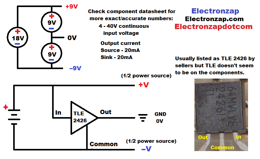
For low power applications, you can easily split a full voltage in half with a TLE2426 rail splitter integrated circuit that comes in a 3 terminal transistor like (TO-92) package. One terminal will output half of the total supply voltage, and can sink or source current to either rail up to it’s maximum current limit. An Op Amp rail splitter version is shown a bit lower down on the page.
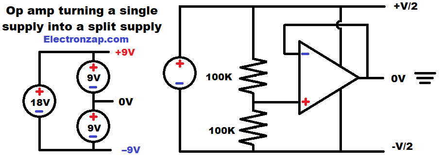
An op amp can easily split a voltage as well. The op amp is a versatile component that comes in many variations. There is a lot to learn about op amps, so I added a op amp schematic page button link near the bottom of this page.
Resistor:
Most resistance based components have a schematic symbol based on a jagged line or rectangle.
A fixed resistor symbol is simply a jagged line, or a rectangle. If the resistor is variable, then their will be a slight alteration to the basic resistor symbol.
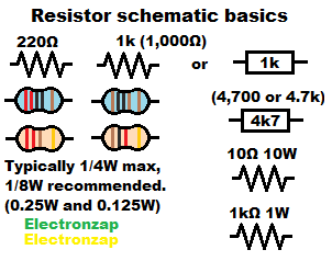
Usually there is a recommended resistance value next to the symbol.
There may also be a recommended minimum wattage value written next to the symbol. Usually that is only if some wattage other than 1/4W should be used. 1/4W should be fine if no wattage value is given, but it is not a bad idea to calculate the wattage just to make sure.
Below are some extra symbols of variations to the basic resistor and diode components.
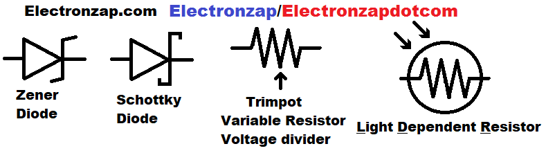
Above are some examples of how the basic resistor and diode symbols can be altered to show a variation.
Simple circuits:
The simplest circuit is just a resistive load and the power supply.
Lines in schematics are used to show how components connect electrically. But they do not tell you how to connect them in a real circuit.
The resistor value that shown on the schematic should be appropriate for limiting current and wattage to a safe amount for the entire circuit at that voltage.
-
-
- If no wattage value is given, it is usually safe to assume that a 1/4W (0.25W) resistor will be alright to use.
-
A bubble with an electrical value (voltage/current/resistance) is often included to show an approximation of what you can expect to see if you measure that electrical property at that point.
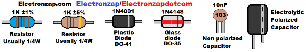
Actual appearance of common components.
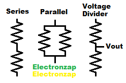
Combining resistors: Series – Parallel – Voltage Divider
-
-
- Series resistors simply add up how much resistance they provide to a series voltage.
- Parallel resistors add up how much current they can pass based the series voltage. More current at a given voltage is the equivalent of less resistance. So, the circuit sees less than resistance than the value of any of the individual resistors connected in parallel.
- Voltage Dividers form when you put a voltage across 2 series resistances, and then measure the voltage where the series resistances connect. You will find that there is a fraction/percentage of that total voltage where the resistances connect together. That divided voltage can be used as a weak (little to no current provided) signal voltage for other circuitry.
-
LEDs:
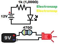
LEDs are a type of diode. Diodes don’t limit current, so something needs to limit the current through them. Often, that is a series resistor.
-
-
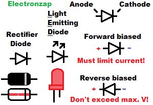
- Light Emitting Diode = LED:
- Anode must be more positive than cathode by about 2 to 3 volts in order to light up. That’s called being forward biased.
- Current won’t flow if the Cathode is more positive than the Anode. As long as you don’t exceed it’s breakdown voltage.
- Current must be limited through diodes. This is often done by adding a series resistor. A recommended value to use is often shown next to the resistor symbol of a schematic diagram.
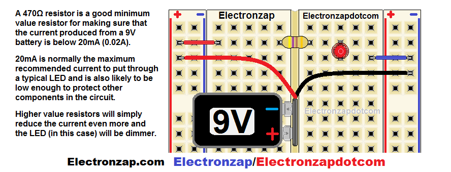
- Common indicator LEDs typically need current limited to no more than 20 milliamps (20mA). That’s the same as 0.02A. 10mA or less will probably be fine. There’s generally no need to try to get all the way to 20mA.
- A series current limiting resistor value is determined by 3 factors.
- The power supply voltage.
- Forward voltage drop of the LED.
- And how much power the resistor will have to dissipate.
-
LED and rectifier diode symbol basics.
-
-
- The physical indicator LED component often looks a bit like a light bulb. Whereas other diodes tend to be cylinders with a band painted near the cathode end.
- Long lead (pronounced like “leed”) of the LED is the Anode. While the short lead is the cathode. That’s assuming that the Anode hasn’t been trimmed yet.
- Other diode types have a band painted on the cathode side.
- Some LEDs have a flattened rim on the Cathode side.
- The band side of the schematic symbol for all types of diodes, is where you want to connect the diode/LED Cathode to the circuit.
- The wide side of the triangle indicates the Anode side of the diode. Notice how the symbol forms an arrow that points in the direction that we imagine how conventional current flows.
- LED schematic symbols simply add arrows pointing away to the basic (rectifier) diode symbol. Indicating it’s ability to emit light.
-
LED circuit built on a breadboard:
If you have a 9V battery snap with stranded wires, you can twist the strands so that they will slide into a prototype breadboard easier. Then you can wire the circuit similar to what is shown below.
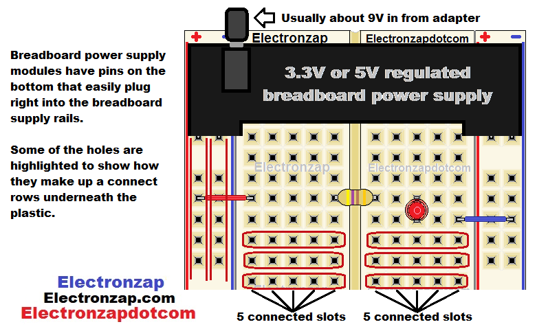
Breadboard power supplies plug into the breadboard and provide power the rails. There’s usually a jumper for each rail that lets you power that rail at 5V, 3.3V, or 0V.
Active Buzzer and push button switch:
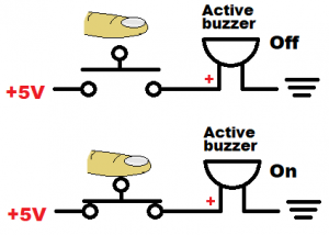
The active buzzer is a useful component that can be connected directly to a voltage that it is rated to be able to handle.
-
-
- Voltage must be limited: Active buzzers are often rated for 5V or less. You need to research the maximum voltage of all components you use.
- Active buzzers are loud and annoying: Usually there is some kind of switch in series with them so that you can turn them off quickly.
-
Push Button switch illustrated on a bread board a bit lower down the page.
Mechanical Switches:
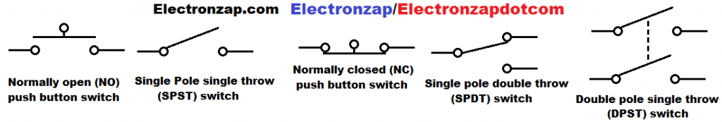
Schematic symbols for mechanical switches usually do a good job of illustrating how the physical component makes connections internally.
-
-
- Open = off: There is no electrical connection.
- Closed = on: There is a direct electrical connection.
- Normally open: Switch is open until you hold it closed.
- Normally closed: Switch is closed until you hold it open.
-
Switches simply alternate between being on or off. But, they have many ways of doing so. Therefore, usually one type of switch makes better sense to use in certain circuits than other types of switches.
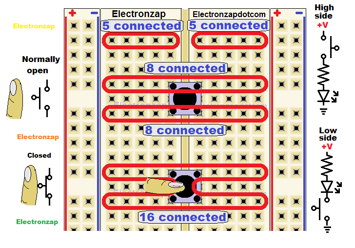
Breadboard Connections: Push Button Switch
One of the best ways to learn electronics is to use a prototype breadboard to build circuits from schematics that you come across.
-
-
- Usually the + (red) and – (blue) rows are all connected from top to bottom
- Middle rows are usually connected 5 across. There’s 2 sets of these rows of 5 across, with a groove down the middle that separates them.
-
Push button switches tend to fit in breadboards reasonably well. You may have to alter the pins so that they fit better, or wait until the slots get used to them. Most of them will likely pop out for a while.
-
-
- Typically, a pushbutton switch has 4 pins (terminals).
- 2 of the pins are always connected to each other, while the other 2 pins are always connected to each other.
- Closing the switch connects both of those 2 sets to each other. While closed, all 4 pins are connected to each other. Therefore also connecting any circuitry on both sides of the switch, to each other.
-
Voltage across resistor:
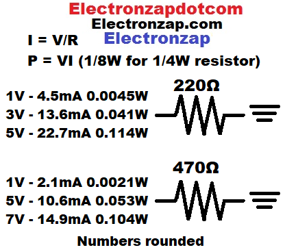
The amount of voltage across a resistance determines the current through it. That is the main principle of Ohms law.
These diagrams show common resistor values.
While studying schematics, you always want to think of the voltages at the various nodes (direct connection points).
For formulas..
-
-
- Current = I (in amps)
- Voltage = V (in volts)
- Resistance = R (in ohms, symbol Ω)
-
I = V/R (current equals voltage divided by resistance.
One thousand ohms is easiest (example below). 10 volts divided by 1 thousand ohms equals 0.01 amps. 0.01A is usually converted to 10 milliamps (10mA).
Multimeter Measurement or Other Notation:
A bubble with an electric value in it is commonly used to indicate what you can expect to measure if you measure at the point. Most of the time, you don’t have to put a meter there.
It’s rare that schematics show detailed circuit voltage, current, and wattage values other than those intended for people starting out. Most schematics assume you can figure out those properties.
-
-
- Voltage measurements: Can be taken at anytime. Knowing the voltage difference at different parts of the circuit is very useful.
- Current measurements: Might be useful. You need to open the circuit and insert the meter. Probably used as a way to verify that the calculated amount of current is actually flowing.
- Resistance: Almost always measured before a component is wired into a circuit.
- There needs to be no other power applied to the component(s) than what the meter provides. The meter may be damaged by another power source.
- Other paths of conduction will alter the resistance measurement.
-
Photodiode:
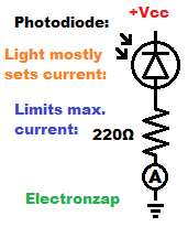
Photodiodes are a type of diode that will pass a certain amount of current based on how much light is falling on it when it is reverse biased.
This circuit uses a series resistor to limit the maximum current based on the supply voltage. Therefore, it is best to limit voltage to no more than about 5V. The photodiode will actually set the current as long as it is below the maximum the resistor sets.
The circled “A” is where you can take a current measurement. Which I did in my YouTube video at Photodiode is an OK light dependent current source demo circuit schematic diagram by electronzap demonstrating this circuit.
Switch and LED:
- There will usually be some kind of switch in series with an LED. Above shows a normally open push button switch. It is open (off) until pressed (closed) and turned on.
- Most real life circuits will have transistors and/or integrated circuits of some kind switching the LED on and off.
Sinking or Sourcing:
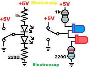
I draw a lot of schematics where you will see a couple of LEDs and protective resistors wired in series. As shown in the diagram.
-
-
- Switch connected to ground: Only the top (blue) LED lights up.
- Switch connected to +5V: Only the bottom (red) LED lights up.
-
A lot of integrated circuit (IC) outputs sink and/or source current in a similar way to what is shown. However, they use internal transistors built onto the “chip” to do so.
That means that the IC output can never make an internal connection directly to Vcc (which is +5V in this case) or ground, the way that a mechanical switch can. Some integrated circuits outputs can connect to Vcc and/or ground better than others. Always consult the datasheet of any IC you use, and build practice (prototype) circuits to get familiar with their limitations.
A voltage different is needed for current flow or to have signals. Being able to follow the current path from the supply voltage to ground is needed in order to read schematics and understand the circuit.
Voltage across LEDs/diodes:
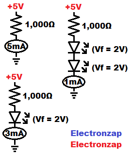
LEDs, and other diodes, can’t limit current on their own. But they do drop voltage. The voltage that they drop, is dropped from series components. Such as from a current setting resistor. Which is any resistor that is being used to set current from a given voltage.
Less voltage across a current setting resistor, results in less current through the resistor. Any series components will have the same amount of current flowing through them, as what is flowing through the resistor.
Here are a couple ways I show voltage drops in schematic diagrams. Usually voltage drops won’t be shown in schematics, but some people add them to help those less familiar with voltage drops.
-
-
- Red LEDs tend to drop about 2V. That’s 2V less across a series resistor that sets current.
- Green and Blue LEDs tend to drop about 3V.
-
If you are using a different color LED than what the schematic designer was planning for, then you might need to make adjustments to your actual circuit to get it to work properly.
You can always stack different types of diodes in order to drop, or output, a desired voltage signal.
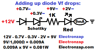
In the adding voltage drops diagram, I show how you can drop a total of 3V from a protective resistor when using a 2V red LED. You take the red LED’s forward 2V drop, then add a forward silicon diodes for 0.7V more drop, and then add a Schottky diode’s forward drop of approx. 0.3V. Giving a total of 2V + 0.7V + 0.3V = 3V drop from the current setting resistor. 12V – 3V = 9V across a 1,000Ω resistor in the diagram. That means 9V/1,000Ω = 0.009A or 9mA of current flows through the circuit.
-
-
- Vf is a common symbol for “forward voltage”. Many people struggle with making the sub f, so using a regular lowercase f after V (Vf) is also commonly used.
-
Multiple connection nodes:
In this first diagram, there are a lot of components that are connected to more than one other component.
Many circuit designers use dots to indicate that there are more than 2 components connected at a node. A node is a direct connection between components.
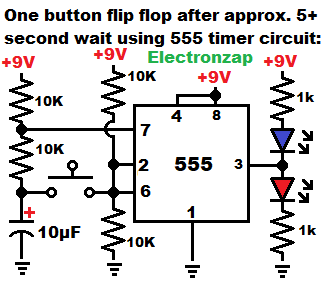
I don’t usually add dots where lines connect. Instead, I usually just indicate non connected lines by using the jump symbol that you see next to the 7 of the 555 integrated circuit symbol.
If a schematic has dots for connected points, then they will just have unconnected lines pass each other.
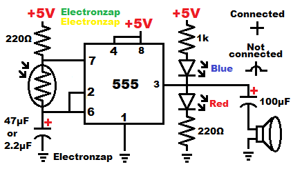
There are no unconnected lines in my second schematic example. I drew it where the lines crossing each other, are connected to each other.
I would have added “Not connected” jumps if there were any lines not connected to each other in this diagram.
The more you understand how components interact with each other, the easier it is to tell if they should be connected or not. Each schematic diagram though should be consistent with how they illustrate connected nodes versus not connected nodes.
I have a similar page for 555 timers at 555 Timer Circuit Schematic Diagrams . Which I will be adding over time. It will help a lot to at least understand capacitors before studying 555 timer circuits and schematics.
Full wave bridge rectifier (with not connected symbol):
Full wave bridge rectifier circuits are one that you learn about early on, but probably won’t make for a while, if ever.
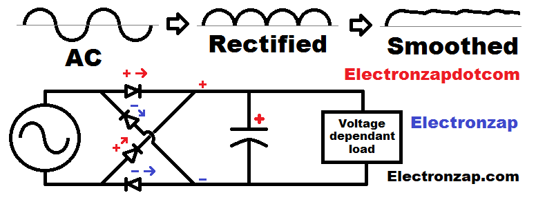
The voltage and current from household and commercial electricity constantly changes directions. 60 times a second in the US.
-
-
- Diodes rectify alternating current. Channeling it so that it provides power of the same polarity to 2 nodes on the other side of the diodes.
- A capacitor is added on the rectified side, as the voltage keeps dropping. The capacitor is instantly charged each time a voltage surge comes along. The capacitor stores charge to keep powering a load when voltage source is at a lower voltage.
-
Notice in the example above, how the diodes direct positive to the top line, and negative to the bottom line as the voltage source keeps changing which side is positive, and which side is negative.
In the example diagram below, negative is pushed to the left, while positive is pushed to the right.
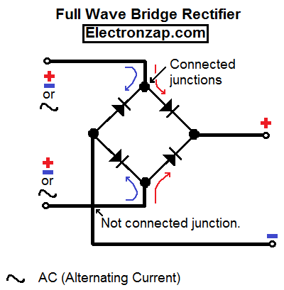
4 diodes are used to convert AC (Alternating Current) to DC (Direct Current) for electronics. They cross over each other with a jump in the diagram above.
No matter which way voltage (and current) is originally applied, 2 diodes make sure that the more positive side heads to the top, while the negative heads to the bottom. The other 2 diodes block that voltage and current from going the other way, until the original voltage and current flips direction. Then it switches which 2 diodes allow it to pass, while also switching which 2 diodes block it.
I drew the second diagram in a way that many people like. Where connected lines are indicated by dots, whereas not connected lines just cross over each other.
Capacitor:
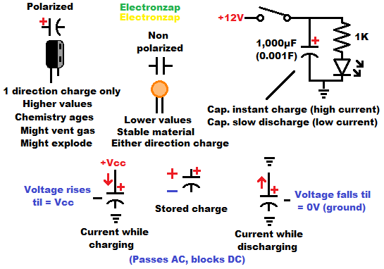
Capacitors store charge. They are similar to little rechargeable batteries, but usually used in very different ways.
-
-
- Polarized: Capacitor needs to be inserted in the correct direction so that only one side can become positive than the other.
- Non polarized: Capacitor can be charged in both directions.
-
Capacitors have 2 close conductive areas called plates. They are separated by an insulator. Electrons can be pulled out of the atoms of one plate while an equal amount of electrons can be placed on the other plate.
Charging Capacitor RC time constant:
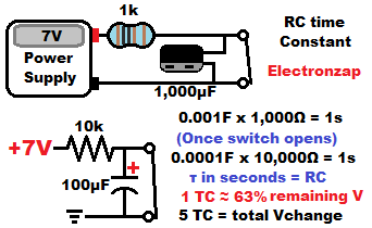
A discharged capacitor has 0V across it. In this circuit, a closed switch will keep the capacitor discharge.
Opening the switch means that the current flowing through the resistor will charge the capacitor. Current will flow into the capacitor until it is charged to the same voltage as the power source.
The closer that the capacitor voltage gets to the supply voltage, less current flows through the resistor, and the long it take for the capacitor voltage to rise.
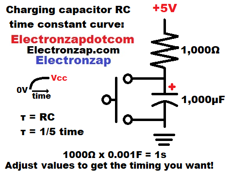
If you measure the voltage change of a charging capacitor through a resistor (RC circuit fragment), you will see a curve similar to the one shown in the second diagram.
A rapid rise at first, and then a slow rise to the final voltage.
Discharging Capacitor:
A capacitor will instantly charge fully if connected directly (or through a closed switch) to a power source.
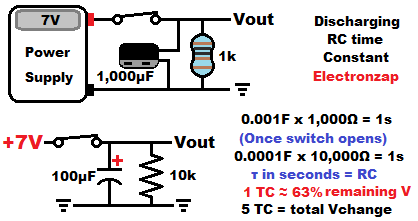
When the switch is open in these circuits, then whatever charge there is in the capacitor, will send current through the resistor, until the capacitor is fully discharged. More current flows while the capacitor has more charge, and thus a higher voltage.
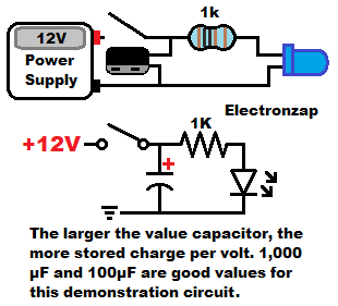
Adding an LED will show that the capacitor is providing current, because current is needed to make the LED light up. The larger the value of the capacitor, the more charge it stores per volt. But, don’t short circuit a capacitor larger than about 1,000µF (one thousand microfarad, which is 0.001 Farad). Large capacitors can move a lot of current. Often enough to vaporize metal.
The discharging capacitor will stop moving current when it’s voltage drops to the forward voltage of the LED at very low current.
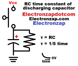
Measuring a capacitor that is discharging through a resistance will show a curve like the one in the final diagram.
The will be a rapid voltage drop at first. That’s when the capacitor has a relatively high voltage. Therefore it is pushing more current through the resistor.
After that initial rapid discharging capacitor voltage drop, a lot less current flows through the resistor, so the capacitor discharges more slowly. Gliding it’s way to 0V difference between the capacitor plates.
Series Resistors:
If you only have 1,000 ohm (1k) resistors, but you need 2,000Ω of resistance, then you can connect two 1k resistors in series.
What ultimately happens, is that the voltage gets divided across the series resistors, based on each ones percentage of the total resistance.
A higher value resistor will have more of the supply voltage across it than a lower value resistor. That is how the same amount of current flows through them, and is also the reason you can use 2 resistances with an output to make a voltage divider.
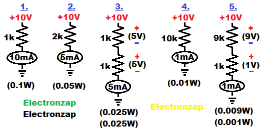
I also showed the calculated wattages for the resistors in the example above. It is important that resistors don’t get too hot. Most are rated for one quarter watt (1/4W or 0.25) but are recommended to stay below 1/8W (0.125W). Resistors convert the combination of voltage and current into heat. Power in watts is the voltage in volts across a resistor, times the current in amps through a resistor.
List of topics:
Below is a list of components and other symbols I have added, or plan to add to this page. They will be combined into circuits. I am working on moving this topic lower down the page, so it will look misplaced for a while.
-
-
- Voltage (power) source:
- Battery.
- Power supply: Either fixed voltage, or adjustable voltage.
- Resistance based components:
- Resistor.
- (Trimmer) Potentiometer/Trimpot: An adjustable resistor and/or voltage divider.
- Light Dependent Resistor (LDR)
- buzzer
- Light bulb.
- DC motor.
- Multimeter measurement and other notations symbols:
- Voltage (V).
- Current (A/I).
- Resistance (R/Ω).
- Forward voltage.
- Semiconductor (diodes only):
- LED.
- Diode (rectifier).
- Zener diode.
- Switch:
- Capacitor:
- Inductor:
- Voltage regulator:
- Voltage (power) source:
-
Voltage and Current sources:
Provides power (voltage times current) to a load.
-
-
- Vcc: Indicates the positive supply terminal of an unspecified voltage difference in relationship to ground. It is primarily used in basic bipolar junction transistor circuits. But, many people use it in any circuit schematic.
- + and – (voltage source) bubble: Is an analytical way to show an unspecified voltage source. It indicates something that will maintain the voltage written next to it, within its limits of course. Not a symbol that is used in most schematics.
- Arrow (current source) bubble: Is circuitry or power source that limits current, no matter what the load is, as long as the load doesn’t limit current even further. Current source needs enough supply voltage to maintain the current through itself and the load
-
-
-
- Battery.
- One cell: One long line and 1 short line with a gap between them.
- 2 cell generic symbol. The diagram shows a 9V battery (probably alkaline) being indicated by a battery schematic of 2 cells. A real 9V alkaline battery has 6 cells. The circuit doesn’t care how many actual cells there are. So, usually the schematic simply shows a 2 cell battery symbol, while you use whatever meets the voltage requirement of the circuit.
- There are rechargeable 2 cell lithium ion batteries that can provide up to 8.4V (only recharge them with a good 2 cell li-ion charger). Since they will often work in 9V based circuits, they are commonly labeled as 9V batteries, even though they really aren’t. They must also never be discharged below 6V.
- Actual number of cells symbol.
-
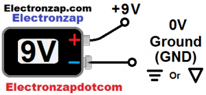
9V battery typical 0V reference ground location diagram by electronzap electronzapdotcom +V GND -V
- Battery.
-
Often the positive terminal of a voltage source is indicated with a + and the amount of voltage that the voltage source has.
The negative terminal is usually considered 0 volts. It is the end point while you are reading a schematic diagram. Therefore it is called ground.
Split/Dual Supply:
There may be a negative voltage in relationship to ground in addition to a positive voltage in relationship to ground.
You aren’t likely to come across any circuits where there is only negative voltages in relationship to ground.
In those cases, 0V ground is a middle voltage. Typically there’s an equal + voltage and – voltage in relationship to ground. +15 to -15 aka. ±15 will be seen from time to time if you look at a lot of schematics.
A ±9V circuit actually has a total of 18V. But +9V has current flowing in one direction to ground, while -9V has current flowing to it from ground.
Split aka. dual supplies are very rare with basic circuits, and probably not all that common at all anymore. They make it easy to alternate current to and from ground.
Other basic circuit fragments/topics:
-
-
- Connected versus not connected lines.
- Resistor symbol can be used as a unknown load symbol: Rload.
- Series LEDs: (more efficient than parallel LEDs)
- Parallel LEDs: (They need their own protective resistor)
- Voltage divider:
- Potentiometer/Trimpot (Trimmer Potentiometer):
- Zener diode:
- Stacking voltage drops:
- Relay:
-
Related pages:
To support this site, check out the following links:
-
-
- Become a Patron!
- Check out my YouTube videos! https://www.youtube.com/c/Electronzap/videos
- Products I used in my videos or otherwise think look like a good buy. As an Amazon associate, I earn from qualifying purchases. https://www.amazon.com/shop/electronzapdotcom
-
-
- Information on this site is not guaranteed to be accurate. Always consult the manufacturer info/datasheet of parts you use. Research the proper safety precautions for everything you do.
- Electronzap is a participant in the Amazon Services LLC Associates Program, an affiliate advertising program designed to provide a means for sites to earn advertising fees by advertising and linking to amazon.com.