Table of Contents
Capacitors do a lot of things for circuits.
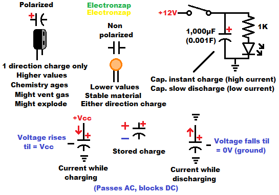
The Schematic symbols for capacitors do a pretty good job of showing how they work. There are 2 conductive areas called plates, which are separated by a insulator.
The plates are specially made to be able to get an imbalances of charges a lot more easily than most conductive material that is separated by an insulator.
You apply a voltage to both ends of the capacitor in order to charge it. Current will flow until the capacitor is the same voltage that is being applied to it.
- Capacitors do not limit current. Large capacitors, or high voltages, can cause damaging current.
- I do have some supercapacitors that limit current, but never just assume that one will.
- Polarized capacitors must only be charged in one direction. Positive to it’s positive terminal, and negative/ground to it’s negative terminal.
A charged capacitor has stored energy. Mostly used to brief power other circuitry or give a signal voltage to other circuitry while it discharges. Super/ultra capacitors, which can store a lot of power, are very expensive and take up a lot of space when compared to batteries.
The amount of stored charge of a given capacitor depends on it’s capacitance in Farads, and how much current over time it has been given.
Charging capacitor RC time constant demo circuit:
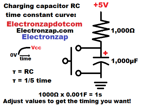
You need to measure the capacitor voltage with an oscilloscope to best benefit from building this circuit.
The capacitor will be fully charged up to supply voltage (5V in the diagram) if the switch hasn’t been pressed for more than 5 seconds.
Never short a large value capacitor, or one that is charged to a high voltage. I only short capacitors that are no more than 1,000µF (0.001F) and are charged to no more than 9V.
Pressing the push button switch instantly discharges the capacitor. It’s voltage drops right down to 0V.
While closed, the switch also passes any current through the resistor directly to ground.
Releasing the switch makes the resistor’s current charge the capacitor. At first, there is a 5V difference across the resistor. 5 volt supply versus a 0V capacitor. That’s when the most current flows through the resistor, and the capacitor will quickly be charged to almost 2/3 of the supply voltage. In about a second in the example diagram. That’s over 3 volts that the capacitor is charged to.
A capacitor charged to above 3 volts through a resistor, with a 5V supply, leaves less than 2V across the resistor. A lot less current flows through the resistor, and the capacitor charges more slowly for a given time. It takes approx. 1 second in the example above for the voltage to rise approx. 2/3 of the remaining voltage difference.
By the end of the fourth time constant (4 seconds in the diagram example) the capacitor is charged to about 98.2% of the supply voltage. There’s so little current flowing through the resistor by this point that it takes a whole time constant to rise the voltage to approx. 99.3%.
Some more current trickles through the resistor for a long time, but by 5 time constants, the voltage is close enough to being 100% of the supply voltage that the capacitor is considered fully charged.
Capacitor discharging demo circuit:
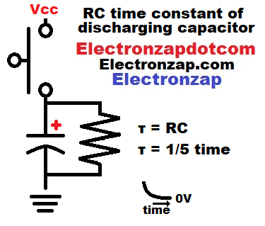
Again, the voltage changes of a capacitor are best observed with an oscilloscope. But if you don’t have one, it still helps a lot to understand how capacitor voltage changes.
Just like while charging, discharging a capacitor through a resistor results in a rapid voltage change at first, but then quickly slows down.
The only difference being that the voltage drops while discharging, whereas it went up while charging.
- One time constant is the capacitance in Farads, times resistance in Ohms. TC = CR.
- Remember that capacitance is usually given in microfarads, whereas the formula is calculated in Farads. So, 1,000µF (one thousand micro farads) would be converted to 0.001F (one one thousandth of a Farad.)
- Instant of TC for time constant, the tau symbol (τ) is often used.
Voltage Ramp: Charging Capacitor
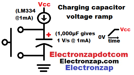
Capacitors have a linear relationship between it’s voltage and the current charging it.
A steady current will change a capacitor’s voltage steadily. The rising or falling line of an oscilloscope measuring that steady voltage change is called a ramp.
Higher value capacitors need more current to raise their voltage at the same speed as a lower value capacitor.
Discharging Capacitor Ramp:
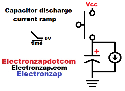
A steady current discharging a capacitor will results in a steady voltage drop.
That voltage will show up as a straight line working it’s way down when measuring with an oscilloscope.
Generally speaking, current sources need a certain amount of voltage across them to maintain the current set through them. So, They will likely stop conducting before the capacitor is fully discharged.
Coming soon:
- Basic fading an LED off with a capacitor circuit:
- Charging RC time constant voltage measured with an oscilloscope:
- Discharging RC time constant voltage measured with an oscilloscope:
This is a new page that will be updated!
Topics to be added:
- Energy Storage:
- Farad: µF (micro Farad):
- Smoothing:
- Voltage based on stored charge (and capacitance):
- Timing:
- Parallel:
- Series:
- Coupling:
- Decoupling:
Related Pages Links:
To support this site, check out the following links:
- Become a Patron!
- Check out my YouTube videos! https://www.youtube.com/c/Electronzap/videos
- Products I used in my videos or otherwise think look like a good buy. As an Amazon associate, I earn from qualifying purchases. https://www.amazon.com/shop/electronzapdotcom
- Information on this site is not guaranteed to be accurate. Always consult the manufacturer info/datasheet of parts you use. Research the proper safety precautions for everything you do.
- Electronzap is a participant in the Amazon Services LLC Associates Program, an affiliate advertising program designed to provide a means for sites to earn advertising fees by advertising and linking to amazon.com.