Table of Contents
Operational Amplifier (Op Amp) and Comparator Integrated Circuit (IC) components are indicated by a triangle with 2 inputs and an output.
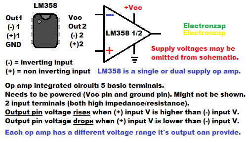
The LM358 is a commonly used Op Amp for those studying basic electronics. So it is the main one I used in my videos and diagrams.
There are 2 op amps in each 358 integrated circuit (IC).
The Op Amp can also be used as a comparator.
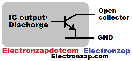
Comparator only ICs have outputs that tend to only connect to ground (low) or turn off (high). That is the case when they are referred to as being “open collector” or “open drain”.
They need a pull up resistor for a high output.
Always consult the manufacturer’s datasheet (do a google search of the part number) of the op amp/comparator that you are using. That’s the best way to learn it’s limitations.
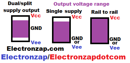
Op Amps tend to have 3 output types. They may fall short of both power rails (dual/split supply), be able to connect to ground almost directly (single supply), or are able to provide both supply voltages (Vcc and GND) if little current is needed (rail to rail).
Consult the datasheet of the part number you have, for the best specifications of it’s output limits.
Assorted integrated circuits (ICs) kit. Included is the LM358, NE555 timers and other commonly known ICs. I have previously covered some of the other ICs in YouTube videos. It is an Affiliate link ad that supports this channel.
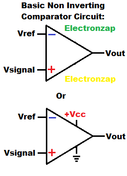
Non Inverting Op Amp Comparator:
Comparator circuits look at 2 voltages. The output’s high or low state depends on which input has the higher voltage.
Inputs:
- Non Inverting (+).
- Inverting (-).
Signals being compared:
- Reference Voltage (Vref).
- Signal Voltage (Vsignal).
Non Inverting Output:
- High output when Vsignal is higher than Vref.
- Low output when Vsignal is lower than Vref.
Op amps are integrated circuits which need to be powered.
The schematic diagram may or may not show the op amp as being powered, but either way you need to connect power to the power pins. I showed both schematic examples above.
Inverting Comparator:
By simply switching the inputs of the non inverting comparator in relationship to reference and signal voltages, you end up with an inverting comparator. Now the reference voltage is applied to the + terminals, while the signal you are comparing it with is connected to the – terminal.
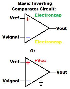
Inputs:
- Non inverting input (+) is the reference voltage.
- Inverting input (-) is the signals that is being compared to the reference voltage.
Output:
- Voltage out is high (as close to Vcc (positive supply) as possible when – input voltage is lower than + input.
- Voltage out is low (as close to GND (negative supply) as possible when – input voltage is higher than + input.
Voltage Follower:
Signal voltages are usually very weak. If current is asked of them, then their voltage will drop rapidly. Followers output the same voltage as the signal, but can maintain that voltage much better while providing current.
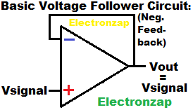
The op amp output goes up or down based on which input has a higher or lower voltage in relationship to the other.
- Non inverting input = +
- Inverting input = –
Negative feed back for the follower consists of the output being directly connected to the – input. That way, the voltage applied to the – input is whatever the voltage of the output is.
- +V more than -V raises output voltage.
- +V less than -V lowers output voltage.
- +V equal to -V holds output voltage steady.
Since the output voltage is the voltage applied to the inverting (-) input, that means that it has to jump right to the non inverting (+) input voltage in order to hold the voltages at both inputs equal.
Current Source:
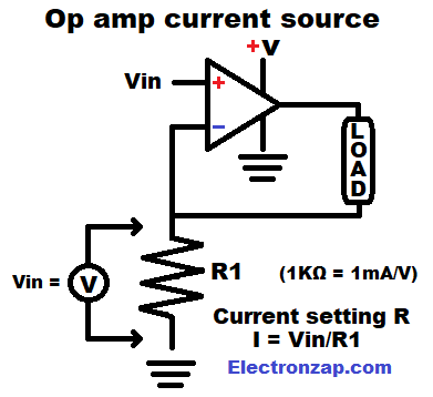
As mentioned above, op amp output with negative feed back moves it’s voltage up or down as needed to match – input voltage to the signal voltage applied to + input.
A load can also be placed in that feed back. The load will drop and/or divide some voltage in this circuit, so the output needs to be able to provide a higher voltage than the signal voltage.
A resistor from – input to ground, gives a current path to ground. This is called the current setting resistor. Remember that the inputs don’t source or sink current other then a very small amount of leakage.
Since the output will make sure that the – input has the same voltage as + input, that will be the voltage across the current setting resistor. The value of the resistor, and the voltage across it, will set the current through it, and the load. That is of course, as long as the output can provide that much current. And also be able to provide enough voltage to meet the voltage across the resistor plus the voltage that the load needs.
Virtual Ground Rail Splitter Op Amp:
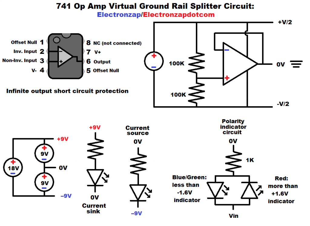
You can split a larger voltage as an alternative to getting/building a dual supply.
- Dual supply power can be made when you connect two 9V batteries in series, but you have some to all of the load circuitry connected to the node (electrical connection) where the two series 9V batteries are connected to each other. That is your 0V ground in such circuits.
- Split supply is when you have a relatively large voltage, and you set a point that outputs half of the total voltage. Commonly referred to as splitting it. Any circuitry connected to that half way point, is going to see voltages that are more positive and/or negative than that voltage. That half way voltage point is typically called a “virtual ground” and is considered as being 0V.
Dual/Split supplies make it easy for the 0V ground to sink or source current. Making it easy to wire alternating current circuits while using power sources that are direct current based.
More to be added!
This is a new page. I will be adding much more!
List of Basic Op Amp Circuits:
I will probably make a separate page for each of these in the future. Then turn the text into a link to that page.
- Non Inverting Comparator:
- Inverting Comparator:
- Non Inverting Comparator Schmitt Trigger (with Hysteresis):
- Inverting Comparator Schmitt Trigger (with Hysteresis):
- Voltage Follower:
- Current Source:
- Virtual Ground Rail Splitter:
- Window Comparator:
Other circuits:
- Non inverting amplifier:
- Inverting amplifier:
- Schmitt Trigger:
- Sample and hold:
- Oscillator:
- Multivibrator:
- Monostable
- Summing amplifier:
- Staircase generator (with reset):
Related pages:
To support this site, check out the following links:
- Become a Patron!
- Check out my YouTube videos! https://www.youtube.com/c/Electronzap/videos
- Products I used in my videos or otherwise think look like a good buy. As an Amazon associate, I earn from qualifying purchases. https://www.amazon.com/shop/electronzapdotcom
- Information on this site is not guaranteed to be accurate. Always consult the manufacturer info/datasheet of parts you use. Research the proper safety precautions for everything you do.
- Electronzap is a participant in the Amazon Services LLC Associates Program, an affiliate advertising program designed to provide a means for sites to earn advertising fees by advertising and linking to amazon.com.