Accumulative light trigger switch circuit – 555 timer and photodiode – Electronics lesson

The total amount of light that falls on the photodiode is what sets the timing of this accumulative light circuit.

Accumulated light trigger circuit using 555 timer and photodiode learning electronics lesson 0063

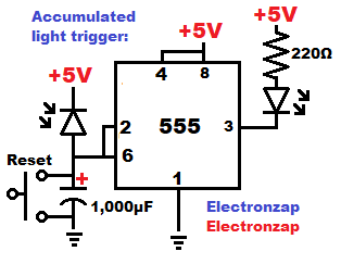
Parts of the circuit.

  • 555 timer integrated circuit: Wired as a (digital) inverter Schmitt trigger. Low input (below 1/3 supply voltage) to pin 2 sets the output High. High input (above 2/3 supply voltage) to pin 5 sets the output low.  Between 1/3 and 2/3 supply voltage is the hysteresis range. That is where the output stays in whatever state it was last put into.
  • Normally open (NO) Pushbutton switch (reset): Instantly discharges the timing capacitor to 0V while being pressed (closed). Does nothing while not being pressed (open).
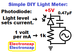
  • Photodiode: While reverse biased the photodiode passes a certain amount of current through it based on how much light is falling on it, but only for as long as there is a voltage different across it. In this circuit, there is a voltage difference across the photodiode for as long as the capacitor is not fully charged.
  • Capacitor: Takes time to charge based on how much current is flowing into it. A 1,000µF capacitor (the same as a 1mF), will take 5 seconds to charge to 5V if charged with 1mA of current. Whereas it will take 10 seconds for it to charge to 5V with 0.5mA of current. Another example is that it will take 2 1/2 seconds to charge to 5V with 2mA of current charging it.
  • LED: Anode is headed to the positive supply. That means that it will not pass current and light up until the Cathode is more negative by about 2V for a red LED, which is usually their forward voltage. The LED will be off while the 555 output is high, due to the pushbutton switch having been pressed in this case, but after the photodiode gets enough light to charge the capacitor to 2/3 supply voltage, then the output goes low (0v), and the LED turns on due to it now having 5V across it and it’s protective resistor.

Video:

To support this site, check out the following links:

This is a new page that will be updated soon!

Home page

  • Information on this site is not guaranteed to be accurate. Always consult the manufacturer info/datasheet of parts you use. Research the proper safety precautions for everything you do.
  • Electronzap is a participant in the Amazon Services LLC Associates Program, an affiliate advertising program designed to provide a means for sites to earn advertising fees by advertising and linking to amazon.com.

Simple DIY light mater using photodiode with resistor and oscilloscope demonstration circuit

Simple DIY light meter using photodiode resistor voltage divider learning electronics lesson 0061

Putting a reverse biased photodiode in series with a 1,000 ohm resistor will result in the resistor having 1 volt across it for every mA of current that the photodiode allows to pass through them.

The light coming from the lamp I was using in my video, adjusts it’s brightness by turning on and off rapidly. To smooth out the voltage I added a 0.47µF capacitor parallel to the photodiode.

An Oscilloscope connected in parallel to the resistor measures the voltage across the resistor. When the light level is low, the voltage stays close to 0 volts as the photodiode is allowing almost no current to flow through.

When my lamp is at it’s brightest setting, the voltage across the resistor gets around 2.5V, depending on how close it is to the photodiode, and how well the photodiode is pointed at the light. 2.5V across the resistor means that the photodiode is allowing 2.5mA to flow.

My headlamp light focuses a lot more light directly on the photodiode, so it makes it go right to 5V.

5 volts seems to work well for powering this circuit. The oscilloscope I use is powered by a 120VAC t0 9C DC adapter.


The photodiodes in the affiliate link ad above have mostly good reviews and probably act like the ones used in my video but are a bit larger. Some reviewers mentioned that they are actually phototransistors, which I suspect is true based on what they said, and my earlier testing of the photodiodes that I bought elsewhere, and have gotten the same results that they did.  Regardless, I will still call them photodiodes for now since that is what they are being sold as and I can’t prove that they aren’t at this time.


Oscilloscope including power adapter from a seller with OK reviews. Affiliate link ad.

Check out these links!

Make sure to subscribe and ring the bell! from r/ElectronicsStudy

Home page

  • Information on this site is not guaranteed to be accurate. Always consult the manufacturer info/datasheet of parts you use. Research the proper safety precautions for everything you do.
  • Electronzap is a participant in the Amazon Services LLC Associates Program, an affiliate advertising program designed to provide a means for sites to earn advertising fees by advertising and linking to amazon.com.

S102 – T Current Regulating Diode CRD – 1mA current source electronics component

Current regulator diode schematic symbol diagram by electronzap

Although it has diode in the name, a Current Regulating Diode (CRD) component does not act like a diode at all. It is a single component current source with 2 terminals. The Anode and the Cathode.

The CRD is actually JFET transistor wired to pass a specific amount of current with the proper polarization (Anode more positive than Cathode).

The CRD is also commonly called a Current limiting Diode (CLD) or a Constant Current Diode.


I got my S102-T from the Joe knows electronics kit above. It has a nice assortments of semiconductors to learn about and experiment with. Amazon affiliate link ad.

Constant current for a zener diode:

Current set through zener diode with Current Regulator Diode circuit schemtic diagram by Electronzap

Zener diodes can only hold their output voltage steady if the current flowing through them is steady (constant).  Therefore, a constant current diode is a good way to keep current through a series zener diode at the same rate, even as the supply voltage changes by a large amount.

The S102 (or the E102) passes 1000 microamps of current, which is the same as 1 milliamp, when it’s Anode is more positive than it’s Cathode by around 2V or more. This was enough current to build up 5.16V across the 5.1V zener diode I testing in the video below.

I also do some current measurements with the multimeter while the CDR is alone, and when it was used to limit current through a series LED.

Some important S102-T component values:

Taken from a datasheet I found that includes the S102-T. Always verify for yourself by finding and reviewing the datasheet of the particular component you are interested in.

  • S series = Surface Mount Device (SMD) type.
  • E series = Leaded component type.
  • The part number 102 stands for 10 followed by 2 zeros = 1000µA. 1000µA (one thousand microamps) is the same as 1mA (one milliamp).
  • S series = 500mW rated power.
  • E series = 300mW rated power.
  • Allowable reverse current = 50mA. Remember that despite the name, the CRD is not actually a diode. Therefore it does not limit current when Cathode is more positive than the Anode.

Check out these links!

Make sure to subscribe and ring the bell! from r/ElectronicsStudy

Home page

  • Information on this site is not guaranteed to be accurate. Always consult the manufacturer info/datasheet of parts you use. Research the proper safety precautions for everything you do.
  • Electronzap is a participant in the Amazon Services LLC Associates Program, an affiliate advertising program designed to provide a means for sites to earn advertising fees by advertising and linking to amazon.com.

JFET N Channel J310 Junction Field Effect Transistor – Idss and adjustable current source

N Channel JFET schematic symbol I like to use and pin layout for TO 92 package J310 diagram by electronzap

JFET transistor components make for an easy current source circuit fragment. Providing a certain amount of current that only varies a little bit over a range of voltages.

The only JFET I have is the N channel depletion mode J310. Therefore it is the one I use in my demonstration circuits.

According to the datasheet I looked at, the J310 has…

  • Idss of 24mA to 60mA
  • Maximum power dissipation of 350mW.

Idss and setting current:

JFET Idss and current setting resistor circuit schematic diagram by electronzap

Connecting both the Source and Gate pins of an N Channel JFET transistor to ground while the Drain is connected to the positive supply voltage, or to a load, will allow the transistor to pass it’s maximum current as long as there is enough voltage.

This is known as it’s Idss.

My J310 passes somewhere around 31mA of current while wired for it’s Idss, as demonstrated in the video below.

According to the datasheet I looked at, a J310 could have an Idss of anywhere between 24mA to 60mA. You have to test each one to know for sure what it’s value is.

0.03A x 5V = 0.15W of transistor power that needs to be dissipated for my J310 at 5V. Therefore I keep the voltage across my J310 to about 5 volts. Only exceeding it by a couple of volts for short periods of times.

Adding a resistor from the Source pin to ground lowers the current passed from Drain to Source below the Idss. In my video below, I used a 100Ω resistor, which sets the current of my J310 to about 10mA at 3-7V with no load and also about 10mA of current at 5-7V with a red indicator LED added in series on the drain side.


I got my J310 from the Joe knows electronics kit above. It has a nice assortments of semiconductors to learn about and experiment with. Amazon affiliate link ad.

Make sure to subscribe and ring the bell! from r/ElectronicsStudy

Home page

  • Information on this site is not guaranteed to be accurate. Always consult the manufacturer info/datasheet of parts you use. Research the proper safety precautions for everything you do.
  • Electronzap is a participant in the Amazon Services LLC Associates Program, an affiliate advertising program designed to provide a means for sites to earn advertising fees by advertising and linking to amazon.com.