Table of Contents
Thought I would devote a single page to a bunch of electronics circuits for those who don’t want to read a lot of text.
Simple circuits with basic components:
Lone resistor/resistive component:
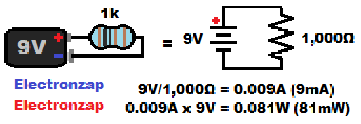
Resistors limit current based on the voltage across them.
They also heat up (power/wattage), and must not be allowed to overheat.
- I = V/R is the Ohms law formula for current:
- Current (I) in amps, though a resistor, is equal to the voltage (V) in volts, across the resistor, divided by the resistance (R) of the resistor, in Ohms.
- P = VI formula for power:
- Power (P) in Watts (W), of a component is the Voltage (V) in volts across it, times the current (I) in amps (A), through it.
- Most resistors are rated for 1/4W (0.25W) maximum. But it is still highly recommended to stay below 1/8W (0.125W).
Measuring circuit current with a multimeter:
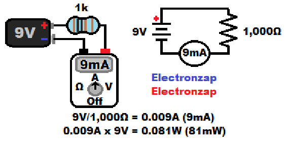
- Current is the same through all series components.
- Measuring current:
- Circuit must be opened.
- The meter must be set to measure a higher amount of current than will be put through it.
- More current through a meter than it is set to measure will damage the meter. Doing so will probably blow a fuse, which will have to be replaced. Luckily, that is not very hard to do.
- Then the meter is connected in series with the components in order to close that opening. The circuit current will then flow through meter freely so that it can measure it. Simply read the display to see how much current is flowing.
- Measuring current ads almost no extra resistance to a circuit. An impossibly perfect (ideal) ammeter/multimeter that is set to measure current, would have literally no resistance at all. Actual meters come close to that ideal.
Common meter probe placement for voltage measurements:
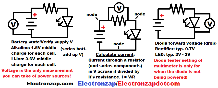
- Set a manual multimeter to measure a voltage higher than you expect to measure. If it is an auto ranging meter, then you just need to set it to measure voltage. Measuring no higher voltage than it’s maximum of course.
- Red probe goes to the more positive side of the voltage, while black probe goes towards the more negative side. If they are connected backwards, and you are using a digital multimeter, then you will simply get the same result, but as a negative voltage on the display.
- Measuring voltage is really safe as long as it isn’t too high of a voltage for the meter. The most damage you can do is usually caused by touching 2 different parts of a circuit with the same probe. Causing a direct electrical connection where there shouldn’t be one is called a short circuit, and high current may flow as a result.
Series resistors:
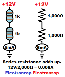
The same current flows through all series components. Therefore, each resistance adds up to a total resistance.
- 2 series 1,000 ohms (1kΩ) resistors provide a total of 2,000 ohms (2k) of resistance to the circuit.
- 12 volts across 2,000 ohms of resistance provides 12V/2,000Ω = 0.006A of current (zero point zero zero six amps). 0.006A is more commonly referred to as 6mA (six milliamps).
- The resistors divide up the voltage (covered in more detail under voltage dividers), which is based on each one of their percentage of the total resistance. Since the current is 0.006A in this example, we can use Ohms law for calculating voltage (V= IR) to find that 0.006A x 1,000Ω = 6V is across each resistor.
- 2 equal value series resistors will always have half of the total voltage across each resistor that is across the 2 of them.
- Always remember that if there are any other components in series with the series resistors, then they will drop or divide away some more of the supply voltage. Unless they are good conductors.
- 6V x 0.006A = 0.036W shows that 1/4W (0.25W max) resistors don’t generate, and don’t have to dissipate, much heat in this circuit.
Resistor voltage dividers:
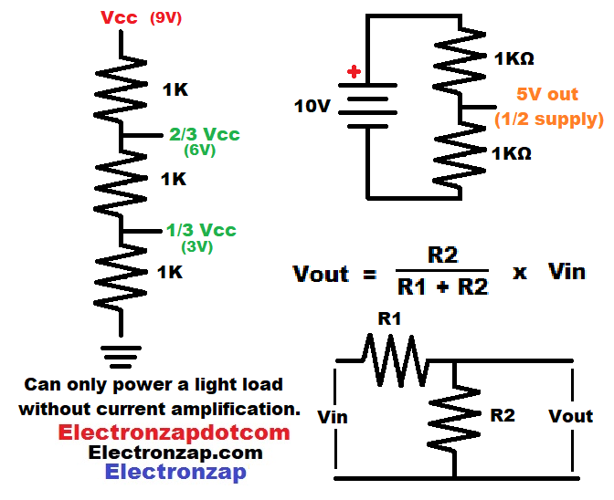
The output voltage of a voltage divider is just used as a signal (not intended to provide current).
- Power (voltage) is applied at the far ends of the series resistors. It is typically the supply voltage directly, but not always.
- Voltage divider output is at the point (node) where the resistors connect to each other. The voltage is usually in relationship to ground (0V/negative side of power supply)
- Two equal value resistors will output half of the total voltage across them.
- Three equal value series resistors have 2 possible output locations.
- The high side (closer to positive) output will be at 2/3 of the supply voltage in relationship to 0V ground.
- Low side (closer to 0V/ground)) output will be at 1/3 of the supply voltage in relationship to 0V ground.
- Two Unequal value resistors (resistances) requires using the formula Vout = R1/(R1 + R2) x Vin to calculate the output voltage. The example calculation given below is for the high (closer to positive/Vcc) side output of the three equal value resistor. Which would also apply to a two resistor output of 2,000Ω low side and 1,000Ω high side voltage divider.
- Vout = 2,000Ω/(1,000Ω + 2,000Ω) x 9V
- Vout = 2,000Ω/3,000Ω x 9V
- Vout = 0.66Ω x 9V
- Vout = 6V
- Vout = 2,000Ω/(1,000Ω + 2,000Ω) x 9V
- Each spot that there is a direct connection between components is called a node.
Parallel resistors:
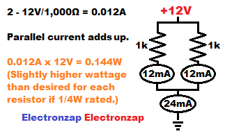
Connecting resistors in parallel always results in an equivalent of less resistance than the lowest value resistor. Two equal value resistors is easy to calculate and analyze.
- Each of the 1,000Ω resistors with 12V across them, in the diagram, will allow 12mA of current to flow through it. Giving a total of 24mA.
- Each resistors also needs to dissipate 12V x 0.012A = 0.144W of power (heat).
- There’s a total of 2 resistors times 0.144W = 0.288 watt of power dissipation as far as the power supply is concerned. But each resistor only has to dissipate half of that total.
- The power supply needs to provide a total of 24mA of current (2 x 12mA) to power both resistors at the same time. The current of all parallel components, adds up to the total circuit current.
- A lone 500 ohm resistor would also provide 12V/500 = 0.024A of current. So, 2 parallel 1,000 ohm resistors have the equivalent resistance of 500 ohms. However, the lone 500Ω resistor would need to dissipate 12V x 0.024A = 0.288W of power. That is too much for the typical 0.25W maximum (less than 0.125W recommended) resistor.
- You can use a 1/2W or higher wattage resistor though.
LED protected by a resistor circuit:
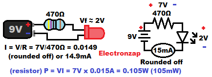
- LEDs (and other diodes) do not limit current on their own and must be protected. However they do drop some voltage. Therefore, there is less voltage across the series resistor, which is still what sets the circuit current in the circuit abive.
- Red or orange LEDs commonly drop about 2V while forward biased.
- Whereas blue or green LEDs commonly drop approximately 3V.
- A series resistor limits the circuit current based on the voltage across it (supply voltage minus LED forward voltage drop), divided by the resistor’s resistance. Ohms law formula I = V/R.
- In the schematic, I showed the voltages across the components when the LED has a forward voltage (Vf) of 2V.
- LED Cathode lead (pronounced like leed) usually comes shorter than the Anode lead as long as the Anode hasn’t been trimmed. Often the Cathode side of the LED also has a flat edge along the rim.
- Anode needs to be more positive than Cathode (forward biased) by it’s forward voltage amount in order to conduct current and light up.
- LEDs can’t block a lot of reverse voltage (Cathode more positive than Anode). They will probably start conducting current at a little over 9V, and then be destroyed.
Series and parallel cells/batteries:
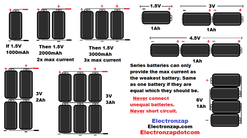
- Series: If you need more voltage than a single cell/battery can provide, you can simply connect more cell/batteries in series (end to end). Only connect the far ends to a current limiting load. Connecting the 2 far ends of series cell/batteries to each other is a short circuit and high current will flow through the batteries, which is usually dangerous.
- Each series cell helps to push the circuit current. Their voltages add up.
- Each cell has the same current moving through them. Therefore they all discharge based on that current flow.
- 1 amp through a 1 amp hour battery will discharge it in an hour, whether or not it is in series with other batteries.
- Parallel: If you need more current to a load, then you can simply add one or more cells/batteries in parallel.
- All of the positives are connected directly together, and all of the negatives are connected directly together.
- Each cell/battery only has to provide a fraction of the total current.
- That means more current can be provided safely, or the same amount of current can be provided for a longer period of time.
- Cells/batteries need to be the same voltage (less than 0.1V different) when connected on parallel. Otherwise high current will result as the higher voltage cells/batteries charge the lower voltage ones.
- Series/parallel: Of course, you can take parallel cells and connect all of them in series with other parallel cells.
- Each series/parallel row needs to have the same voltage and capacity (amp hour) as the other ones.
- It is best to use batteries that were made by the same manufacturer, at the same time.
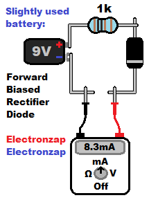
Forward and reverse biased rectifier diode current measurements with a multimeter:
Always keep in mind, that when a circuit with 1 or more diodes/LEDs looks like it is wired properly but no current is flowing. A diode/LED could have accidently been wired backwards (reversed biased when it was meant to be forward biased).
In that case, all you have to do is turn the diode/LED and the circuit should work.
This is more of a bonus circuit for better familiarizing yourself with electronics than a practical circuit. Any time you see a diode in a circuit, you need to think of the effects of it’s voltage drop.
- Most FB (forward biased) diodes, which are silicon based, drop about 0.7V. Which is closer to 0.6V at low current.
- a 9 volt battery, with a 0.7V diode drop, will result in 8.3V across the current setting resistor.
- A 1,000Ω resistor with 8.3V across it will pass 0.0083A of current. 8.3V/1000Ω = 0.0083A. Remember that 0.0083A is the same as 8.3mA.
When measuring current, you need to open the circuit, and you need to make sure that the meter is set to be able to measure more current than you will put through it. Otherwise it my be damaged (blown fuse). Then you complete the circuit by connecting the multimeter in series with the components so that the current also flows through the meter.
A forward biased diode (Anode more positive and cathode more negative) will conduct fairly easily. But, most FB diodes still drop about 0.7V from the current setting resistor.
A band is painted on the cathode side of most diodes. Usually the band is gray, black or red. Whichever stands out best considering the color of the body of the diode.
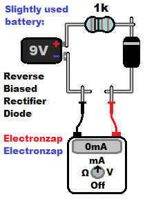
A reverse biased rectifier diode blocks current up to the breakdown voltage of that particular diode. Do not exceed that breakdown voltage. Zero amps/milliamps will show up on the meter. If the meter is sensitive enough though, you may be able to measure the leakage current, which will likely be in the nano, or micro amps range.
No diode ever completely eliminates current flow, but while a rectifier diode is reverse biased, it is usually such a small amount of current leaking through that it doesn’t matter to almost any circuit. Some diodes do have more leakage than others, so that is something to be aware of if you have a circuit where leakage may be a problem.
The 1N4001 is a rectifier diode that is usually included in beginner electronic component kits. It is rated to block up to 50V while reverse biased.
Alternating LEDs by sinking or sourcing current circuit:
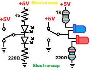
When you see LEDs flashing back and forth, it is likely that the output of something (in this case a single pole single throw switch) is alternating between sinking and sourcing current.
- Schematic diagram, on the left, has the switch set so that it is sinking current. That causes the top LED to be lit up. Current is imagined as flowing from +5V, through the 1k (one thousand ohm) resistor, then the LED, and finally through the switch to ground.
- Pictorial diagram, on the right, has the switch sourcing current. It is imagined that the current is flowing from +5V, out of the switch (output), through the red LED, through the 220 ohm resistor, and then to ground.
- Blue LEDs tend to be a lot brighter than red LEDs when they have the same amount of current flowing through them. So I used a much higher value resistor to limit the current trough the blue LED. Blue LEDs also usually have a forward voltage of about 3V. Whereas red LEDs usually have a forward voltage of about 2V.
- Blue LEDs are much more efficient than red LEDs. The same amount of light needs a lot less power. Power is voltage times current.
Mechanical switch – High side versus low side:
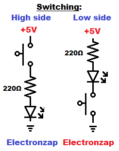
- High side switching is more common. The switch is place closer to the positive side of the power supply while the load is closer to ground.
- Low side switching is also possible. The switch is closer to ground while the load is closer to the positive side of the supply.
- An open switch is “off”. No power will be applied to a load that is in series with an open switch.
- A closed switch is “on”. Power will be applied to a load that is in series with a closed switch.
- Schematic shown here displays a normally open push button switch. It is open/off until you press and hold the button to close/turn it on.
Series LEDs:
Series components share the same current. This is good for multiple LEDs and other low power components for a number of reasons.

- Relatively High voltage can be used to power LEDs that are connected in series because all of their forward voltage drops add up. You can add them in series as needed to drop the supply voltage away from the current limiting resistor until you get an acceptable voltage. Keep in mind that you can get electrocuted somewhere above about 40 volts. Stay away from high voltage!
- 220Ω resistor protecting a single LED from 12V will result in too much current for the LED and too much heat for the resistor. But 4 series red LEDs will usually drop about 8V total from the current setting resistor. 4 series blue or green LEDs will usually drop a total of almost 12V from the resistor. You may need more voltage, even though those LEDs are usually brighter than red LEDs at low current.
- Four series LEDs that are red, each of them usually having a 2V forward voltage, will drop a total of 4 x 2V = 8V from a 12V power supply. That leaves 4 volts across the series current setting resistor. Giving us 4V/220Ω = 0.018A of current through the entire circuit. And 0.018A x 4V = 0.072W of power (heat) that must be dissipated by the resistor. Remember that most resistors are 1/4W resistors, which means that they are rated for a maximum of 0.25W, but recommended to stay below 0.125W of power.
Parallel LEDs with a single protective resistor (should be avoided):
It is best to give each parallel LED it’s own protective resistor. Parallel LEDs of the same forward voltage, with a single resistor protecting them, will split up the current. But not necessarily evenly, and quite likely that it will be very uneven.
If one parallel LED has a higher forward voltage than the other(s), then it will not pass any of the current. Whereas the lowest forward voltage LED(s) will pass all the current.
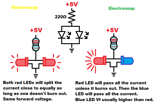
A slightly higher voltage does build up across a FB (forward biased) diode as the current that flows though it goes up. So current might still start flowing through a parallel diode with a slightly higher Vf (forward voltage) than what is in parallel with it. Such as if they are within about 0.1V to 0.2V Vf of each other, for most diodes. Many circuits are sensitive to the exact voltage across a diode as current changes. So it is good to know the voltage across it over a wide range of currents.
Zener diode reference voltage:
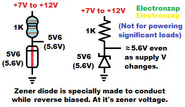
- Zener diodes are specially made to conduct current while reverse biased (RB).
- Zener diodes come in a lot of values at which they are rated to conduct current while RB.
- The voltage that a specific zener diode is rated to conduct while RB is called it’s zener voltage.
- Their value is usually written on them, but it’s very small writing that needs magnification to read.
- When a RB zener diode is conducting current, the zener voltage builds up across it. It does change slightly based on how much current is flowing through it. Upwards at higher current and downwards at lower current. The closer that you get to using a 6V zener diode, the closer it will probably stay nears it’s zener voltage.
- The voltage across the zener diode can be used as a relatively steady reference voltage, even as the power supply voltage changes. Always remember that current through a zener diode still needs to be limited.
- Current must be limited through the zener diode, usually with a resistor. The power supply voltage most be high enough to push current through both the RB zener diode and the series current limiting resistor. A supply voltage of 2V higher than the zener diode, or more, will probably be enough.
- The output voltage is just a signal. A load that need current will probably need amplifier circuitry.
Light Dependent Resistor LDR voltage divider circuit fragment:
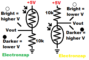
Wired as a voltage divider…
- High side (closer to positive supply) LDR will output close to the supply voltage (5V in this circuit) under bright light. And close to 0V when it is dark.
- Low side (closer to ground) LDR will output close to ground voltage (0V in this circuit) under bright light. And close to 5V when it is dark.
- An in-between light level will output an in-between amount of voltage.
- The value of the fixed (not adjustable) resistor will help determine light sensitivity in relationship to output voltage.
Capacitor storing some charge (Smoothing voltage):
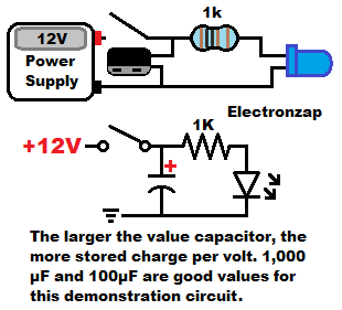
Applying a voltage to a capacitor, charges the capacitor until it is storing enough charge to have the same voltage applied to it.
Power sources that don’t limit current, instantly charge capacitors if connected directly to them. Therefore it is important to only instantly charge relative low value capacitors. I limit it to about 1,000µF, (one thousand micrfarads). 1,000µF is the same as 0.0001F.
Putting an LED protected by a series resistor, in parallel with the capacitor, allows the capacitor to discharge once the power source is removed. The LED stays lit up for a bit. Giving you an indication of how much capacity (energy that can be stored) a capacitor has.
Most power sources can easily charge a capacitor instantly, while powering a load at the same time.
Larger value capacitors keep the LED lit for a longer period of time after the supply voltage is removed. Even a 1,000µF capacitor won’t keep an LED lit for very long though. Don’t plan on using capacitors to store a lot of energy. Rechargeable batteries are far more practical.
The LED fades off in this circuit. Quickly at first and then slower as the capacitor keeps discharging through the load. It’s voltage drops based on how much current it has had to provide.
Good pages to check out next:
To support this site, check out the following links:
- Check out my YouTube videos! https://www.youtube.com/c/Electronzap/videos
- Products I used in my videos or otherwise think look like a good buy. As an Amazon associate, I earn from qualifying purchases. My Amazon affiliate page showing products I think look good
- Information on this site is not guaranteed to be accurate. Always consult the manufacturer info/datasheet of parts you use. Research the proper safety precautions for everything you do.
- Electronzap is a participant in the Amazon Services LLC Associates Program, an affiliate advertising program designed to provide a means for sites to earn advertising fees by advertising and linking to amazon.com.