Table of Contents
Putting a voltage across series resistances, results in a fraction of that voltage between the series resistances.
Equal value series resistors are the easiest to understand.
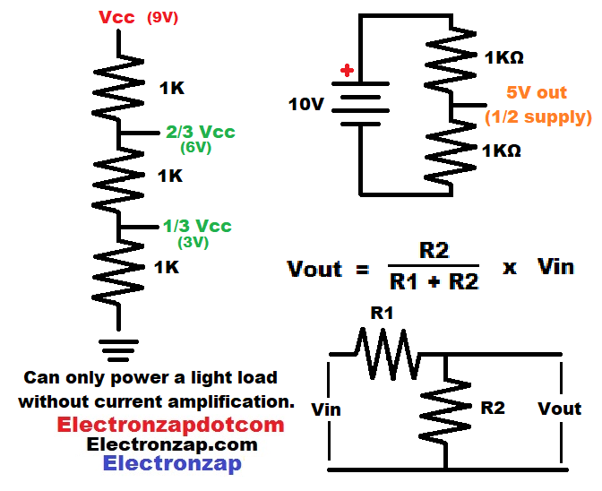
- Two equal value resistors will have half the voltage between them in relationship to ground. With 10 volts across them, they will have 5 volts between them
- Three equal value series resistors have 2 voltage divider nodes.
- High side (closer to positive supply) voltage divider node will have 2/3 of the supply voltage across it. Which will be 6V, if there is a 9V supply across them.
- Low side (closer to negative supply) voltage divider node will have 1/3 of the supply voltage across it. Which will be 3V, if there is a 9V supply across them.
Calculating the voltage at a node examples:
- Formula: Voltage out (of node while being measured) = (low side) resistance “2” divided by the sum of (high side) resistance “1” and Resistance “2”. The result is multiplied with the supply voltage. Vout = R2/(R1 + R2) x Vin
- Two series 1,000Ω resistors powered by 10V:
- 1,000Ω/(1,000Ω + 1,000Ω) x 10V
- 1,000Ω/2,000Ω x 10V
- 0.5 x 10V = 5V output signal voltage.
- High side voltage divider of three 1k resistors in series with 9V across them:
- (1,000Ω + 1,000Ω)/(1,000Ω + (1,000Ω + 1,000Ω) x 9V
- 2,000Ω/(1,000Ω + 2,000Ω) x 9V
- 2,000Ω/3,000Ω x 9V
- 0.66… x 9V = 6V output signal voltage.
- Low side voltage divider of three 1k resistors in series with 9V across them:
- 1,000Ω/((1,000Ω + 1,000Ω) + 1,000Ω) x 9V
- 1,000Ω/(2,000Ω + 1,000Ω) x 9V
- 1,000Ω/3,000Ω x 9V
- 0.33… x 9V = 3V output signal voltage.
- Two series 1,000Ω resistors powered by 10V:
Signal voltages are not meant to provide power. Any current needed from the output results in the equivalent of less resistance on that side of the voltage divider. Therefore, it throws off the signal voltage.
Signal voltages are meant primarily for high impedance (resistance) inputs, which look at the voltage and responds to it, without needing any noticeable amount of current from it.
Video:
To support this site, check out the following links:
I really like the kit above for a single purchase to learn basic electronics and Arduino. This is an affiliate link ad, so I earn from qualifying purchases.
- Become a Patron!
- Check out my YouTube videos! https://www.youtube.com/c/Electronzap/videos
- Products I used in my videos or otherwise think look like a good buy. As an Amazon associate, I earn from qualifying purchases. https://www.amazon.com/shop/electronzapdotcom
- Information on this site is not guaranteed to be accurate. Always consult the manufacturer info/datasheet of parts you use. Research the proper safety precautions for everything you do.
- Electronzap is a participant in the Amazon Services LLC Associates Program, an affiliate advertising program designed to provide a means for sites to earn advertising fees by advertising and linking to amazon.com.