Table of Contents
Two NAND gate Set/Reset (SR) circuit lets you have one output high while the other output is low. A low (usually close to 0V) signal, applied to either the set or reset, determines which output is high, and which output is low.
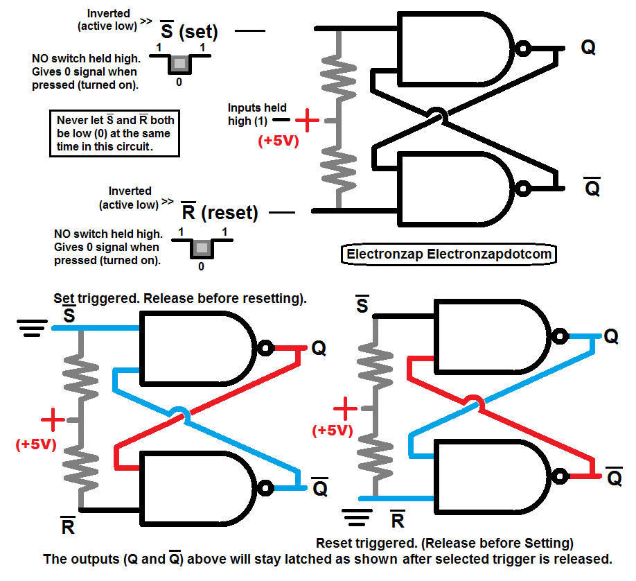
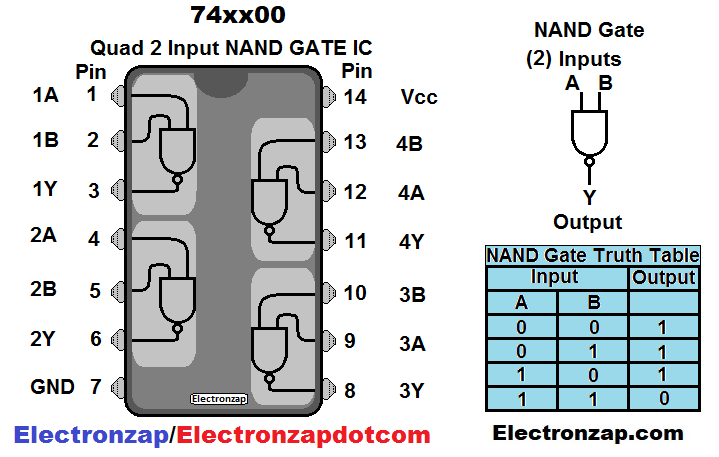
- NAND output will only go low if both inputs are high. If one, or both inputs are low, then the output will be high.
- One input of both of the NAND gates is held high through a pull up resistor and will stay that way until a low input overpowers it. The other input is set by the other NAND gate’s output.
- When one NAND gate output is low, then it gives that low signal to the input of the other NAND gate. As long as the other input of the second NAND gate isn’t forced low, then the pull up resistor keeps that input high, and it’s output stays high.
- Now the second NAND gate feeds it’s high output back to the input of the first NAND gate. Since the first NAND gate’s other input is held high (unless forced low), it has 2 high inputs, which holds its output low.
To support this site, check out the following links:
- Become a Patron!
- Check out my YouTube videos! https://www.youtube.com/c/Electronzap/videos
- Products I used in my videos or otherwise think look like a good buy. As an Amazon associate, I earn from qualifying purchases. https://www.amazon.com/shop/electronzapdotcom
- Information on this site is not guaranteed to be accurate. Always consult the manufacturer info/datasheet of parts you use. Research the proper safety precautions for everything you do.
- Electronzap is a participant in the Amazon Services LLC Associates Program, an affiliate advertising program designed to provide a means for sites to earn advertising fees by advertising and linking to amazon.com.