Table of Contents

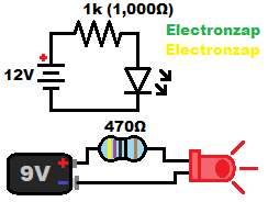
Schematics are drawings of circuits which use symbols to represent actual electrical components.
Pictorials on the other hand, use drawings, or pictures, of the actual components in a circuit.
Always remember that schematics are simply guides that tell you where to make connections. You have to figure out how to actually build it, and modify it, yourself.
Schematic diagrams usually have a recommended power supply voltage, and component values labeled on them. But it is important to learn how to modify every part of the circuit to meet your needs and/or limitations.
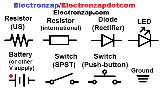
Some commonly used schematic symbols are shown below.

These symbols will show up often in basic electronics schematic diagrams.
Power source:
Usually you use whatever power source works best for you. But, the schematic diagram will have a certain way of showing the power source.
- Battery symbol (2 cell generic symbol), usually with a recommended voltage next to it.
- Makes it easier to visualize the circular nature (loop) of a circuit. Does not necessarily represent 2 chemical cells (battery).
- Might actually be one cell.
- Could be three or more cells.
- Any other type of power supply can be used instead of a battery as long as the proper voltage is applied.
- Makes it easier to visualize the circular nature (loop) of a circuit. Does not necessarily represent 2 chemical cells (battery).
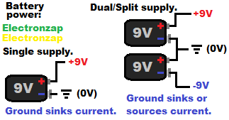
- Positive voltage difference in relationship to 0V ground. Possibly also a negative voltage in relationship to 0V ground for split/dual power supplies. Ground symbol shows where 0V ground is. Ground is the negative side of the power supply as long as there is no voltage more negative than 0V ground:
- +5V or just 5V and a ground symbol (⏚) means that it is a 5 volt power supply.
- +6V (6V) and ground symbol (⏚) or GND = a 6 volt supply. Probably 4 fresh alkaline cells connected in series. Usually single cell “batteries” that are AA in size.
- +12V and ⏚ or GND is common in vehicle or backup battery power applications.
- Vcc and GND. Possibly also Vee.
- Based on the NPN bipolar junction transistor (BJT) Collector and Emitter pin locations.
- Or, Vdd and GND. Possibly also Vss:
- Based on the N Channel MOSFET Drain and Source pin locations.
- Actual number of battery cells symbol:
- Emphases the number of cells that a certain chemistry will need.
- S = series.
- P = parallel.
- 2S2P = 2 series (cells) and 2 parallel (cells). 4 total batteries connected for twice the voltage and twice the capacity.
- 9V alkaline batteries actually have
- Emphases the number of cells that a certain chemistry will need.
- Circle with plus on positive side, and minus on the negative side of the power source:
Schematics typically show one or more of the following power source suggestions…

Not always shown
– voltage regulator (voltage shown is set by dropping some of a higher supply voltage.
– buck/boost (power is converted to change the voltage).
My portable power supply for example, takes in 120VAC and outputs anywhere from 0V to 30VDC. My schematics just show the voltage I set to output, with no mention of how I obtain it.
– Inverter: DC power, usually of lower voltage, is converted into relatively high voltage AC. Usually 120VAC in the United States.
Multimeter:

To be added later!