Table of Contents
Single pushbutton switch alternating LEDs requires a better conductive path through the switch when it is closed than when it is open.
- Vcc can be 5V if the LEDs are red. Higher voltage version shown further down page.
- Vcc can be 9V if the LEDs are blue or Green. 2 Blue or Green LEDs drops more than 5V, so almost no current will flow through them if only 5V is used.
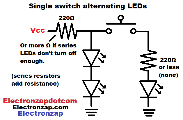
Remember that you need enough resistance to keep the current through the LEDs below 20mA. The resistance must also keep the wattage to less than half of 1/4W (0.25W) for each resistor. Assuming that they are 1/4W resistors of course.
- 2 series LEDs with a forward voltage of 3V (blue or green) will drop 6V. That means a 220Ω resistor will protect them from 9V. However, the single LED will only drop about 3V, so you’d want another 220Ω resistor in series with it if using 9V.
- 2 series LEDs with a forward voltage of 2V (red or orange) will drop 4V. That means a 220Ω resistor will not protect them from 9V. You will want 330Ω to protect them The single LED will only drop about 3V, so you’d want another 220Ω resistor in series with it.
- Of course, you can simply use a single 470Ω resistor to protect all the LEDs from 9V. That is what is shown in the example below.
Video:
Updated video and diagram:
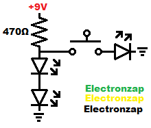
The open switch lets the current from the resistor flow through the 2 LEDs. They will light up as they have a forward voltage of about 4 to 6 volts and 9V is powering the circuit.
Closing the switch also connects a single LED to the current setting resistor. The single LED has a forward voltage of about 2-3 volts. That is half the forward voltage of 2 LEDs with the same forward voltage.
Once the single LED starts conducting, it will limit the voltage across it to it’s forward voltage.
Since the single LED (and the switch) are parallel to the 2 series LEDs, the single LED will keep the voltage below what the 2 series LEDs need to conduct. Therefore all of the current will flow through the single LED, and the 2 series LEDs will not light up for as long as the switch is closed.
Brief Circuit Schematics with Short Video List of Pages
To support this site, check out the following links:
- Become a Patron!
- Check out my YouTube videos! https://www.youtube.com/c/Electronzap/videos
- Products I used in my videos or otherwise think look like a good buy. As an Amazon associate, I earn from qualifying purchases. https://www.amazon.com/shop/electronzapdotcom
This is a new page that will be updated soon!
- Information on this site is not guaranteed to be accurate. Always consult the manufacturer info/datasheet of parts you use. Research the proper safety precautions for everything you do.
- Electronzap is a participant in the Amazon Services LLC Associates Program, an affiliate advertising program designed to provide a means for sites to earn advertising fees by advertising and linking to amazon.com.