Table of Contents
A small amount of NPN Bipolar Junction Transistor (BJT) base to emitter current allows a lot of collector to emitter current.
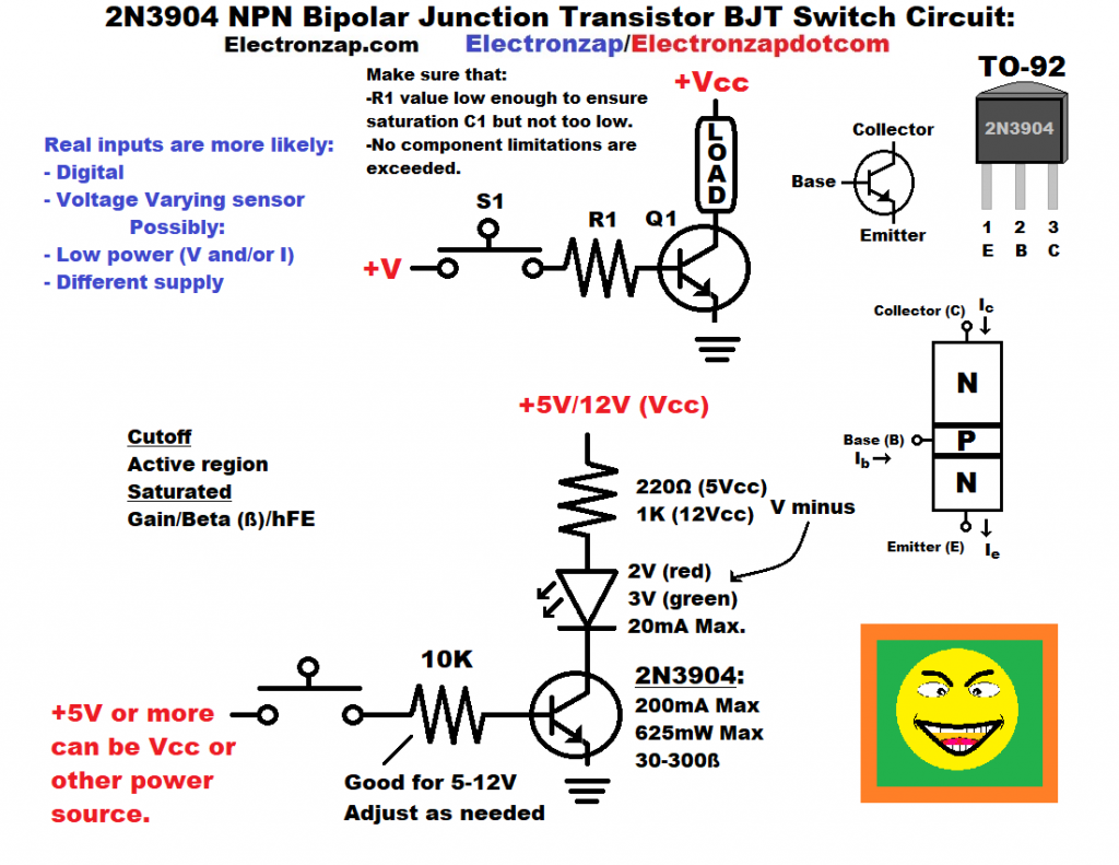
- Closing the switch lets a small amount of current flow from NPN BJT Base to Emitter. that allows many times (usually at least 100 times) as much current flow from collector to emitter.
- The load will end up setting the collector to emitter current as long as the base current and gain are high enough.
- Transistor switches need to saturate. Saturated is when they conduct freely while on. At least better than what the load needs.
- Bipolar Junction Transistor switches also need to cut off. That is when they don’t conduct at all while off.
- The load will end up setting the collector to emitter current as long as the base current and gain are high enough.
You rarely use a mechanical switch to control an NPN BJT wired as a switch. This circuit is more for helping learn basic electronic principles. Normally you end up with other circuitry that can’t provide the power needed to switch the load by itself, but has plenty of power to switch a transistor.
Video:
Brief Circuit Schematics with Short Video List of Pages
To support this site, check out the following links:
- Become a Patron!
- Check out my YouTube videos! https://www.youtube.com/c/Electronzap/videos
- Products I used in my videos or otherwise think look like a good buy. As an Amazon associate, I earn from qualifying purchases. My Amazon affiliate page showing products I think look good
- Information on this site is not guaranteed to be accurate. Always consult the manufacturer info/datasheet of parts you use. Research the proper safety precautions for everything you do.
- Electronzap is a participant in the Amazon Services LLC Associates Program, an affiliate advertising program designed to provide a means for sites to earn advertising fees by advertising and linking to amazon.com.