Table of Contents
A flash of light, that is bright enough, will trigger this monostable mode 555 timer circuit. The load is an active buzzer, which will buzz for as long as the output is high.
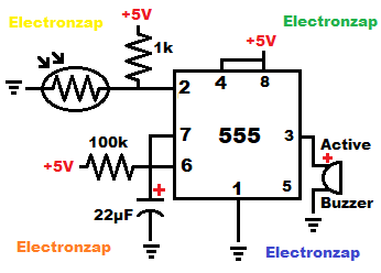
The capacitor stays discharged while the output (pin 3) is low. That is because pin 7 (discharge pin) is connected to ground when the output is connected to ground..
A low output is connected to ground inside the integrated circuit (IC).
A low input (less than 1/3 supply voltage) to pin 2 (trigger) sets the output high, and makes it so that pin 7 stops discharging to ground. Pin 7 acts like a switch that has been turned off, and the capacitor starts charging to at least 2/3 supply voltage through the timing resistor connected to the positive supply to pin 7.
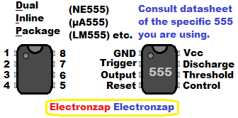
Assorted integrated circuits (ICs) kit. Included is the NE555 timers and other commonly known ICs. I have previously covered some of the other ICs in YouTube videos. It is an Affiliate link ad that supports this channel.
Once the capacitor charges to 2/3 supply voltage, then the output goes low, pin 7 connects to ground and it discharges the capacitor instantly. That is, as long as pin 2 isn’t less than 1/3 voltage. The current flowing through the resistor to pin 7, goes right to ground through pin 7. Making it so that the capacitor stays completely discharged.
However, if pin 2 is low (less than 1/3 supply voltage) when the capacitor charges to 2/3 of the supply voltage, then nothing changes and the capacitor keeps charging. Pin 2 over powers pins 6 (threshold). Pin 6 monitors whether or not the capacitor voltage is at least 2/3 of the supply voltage.
Almost no current flows in or out of pins 2, 4, or 6. They just look at the voltage applied to them, but a small amount of current does sneak through. Not enough to noticeably effect most signals applied to them however.
If pin 2 rises above 1/3 supply voltage, while pin 6 is above 2/3 supply voltage, then the output instantly goes low, and pin 7 connects to ground. At the same time, pin 7 instantly discharges the capacitor.
The output simply stays low for as long as pin 2 is above 2/3 supply voltage, and pin 6 is below 2/3 supply voltage. That is the one (mono) stable state. That is why this is a monostable circuit.
The light dependent resistor is on the low side of a voltage divider. It is connected between pin 2 and ground. There is a fixed value resistor, which is also connected to pin 2, but it goes to the positive supply.
The fix value resistor pulls the voltage up, while the light dependent resistor (LDR) pulls the voltage down. When the LDR voltage is half of the value of the fixed value resistor, then the voltage divider voltage is 1/3 of the supply voltage. If the LDR resistance drops even lower than that due to more light falling on it, then the voltage divider voltage drop even lower.
Video:
To support this site, check out the following links:
- Become a Patron!
- Check out my YouTube videos! https://www.youtube.com/c/Electronzap/videos
- Products I used in my videos or otherwise think look like a good buy. As an Amazon associate, I earn from qualifying purchases. https://www.amazon.com/shop/electronzapdotcom
- Information on this site is not guaranteed to be accurate. Always consult the manufacturer info/datasheet of parts you use. Research the proper safety precautions for everything you do.
- Electronzap is a participant in the Amazon Services LLC Associates Program, an affiliate advertising program designed to provide a means for sites to earn advertising fees by advertising and linking to amazon.com.