Table of Contents
A light controlled switch can be made with a PNP Bipolar Junction Transistor (BJT) and Light Dependent Resistor (LDR)

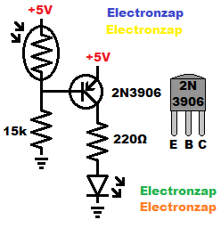
In the circuit shown to the right, the transistor and LED are on when little light falls on the light dependent resistor (LDR).
A fair amount of light will turn the transistor and LED off.
Here is a affiliate link ad to a LDR (photoresistor) kit that I bought and use in my videos.
When it is dark, the LDR barely conducts. Therefore there is an easy path to ground (0v). A little current will flow from emitter to base and then the through the low side resistor to ground. The emitter to base (diode) drops about 0.6V, and then the current is set by the 15,000Ω resistor.
- 5V – 0.6V = 4.4V across the 15k base resistor if it is completely dark.
- 4.4V/15,000Ω = 0.00029333A (or 0.29333mA) of current of base current. Approximately, and if it is completely dark of course.
On the other hand, when there is enough light, the LDR doesn’t have much resistance. That gives the base almost 5V since there is almost a direct connection to 5V through the LDR. The LDR under bright light has far less resistance than the 15,000Ω of resistance going to ground.
With 5V at the emitter, and almost 5V at the base, that means that there is not enough voltage difference (needs at least 0.6V) to get current to flow from emitter to base.
- No emitter base to current means that the PNP BJT won’t let current flow from emitter to collector. The LED is in series with the collector, so it won’t get voltage, or current from the positive supply. The LED has no current flow, so it is off and therefore not lit up. The BJT is considered cutoff at this time.
- A little current from PNP emitter to base will allow many times that amount of current to flow from emitter to collector. There is probably a gain of 100 to 300 times as much current when using a 2N3906.
- Under bright enough light, the transistor should conduct better than the LED and it’s protective resistor. Therefore, the PNP BJT is considered fully on (saturated) and the LED with resistor load will be what is limiting the collector current.
To support this site, check out the following links:
- Check out my YouTube videos! https://www.youtube.com/c/Electronzap/videos
- Products I used in my videos or otherwise think look like a good buy. As an Amazon associate, I earn from qualifying purchases. https://www.amazon.com/shop/electronzapdotcom
- Information on this site is not guaranteed to be accurate. Always consult the manufacturer info/datasheet of parts you use. Research the proper safety precautions for everything you do.
- Electronzap is a participant in the Amazon Services LLC Associates Program, an affiliate advertising program designed to provide a means for sites to earn advertising fees by advertising and linking to amazon.com.