Table of Contents
Op amp, and comparator integrator circuits (ICs), are always comparing the voltages at the inverting input and the non inverting input.
Without feed back you have a comparator circuit. One of the input voltages is always higher than the other.
The output will be
- High when + has a higher voltage than -.
- Low when + has a lower voltage than +.
Feed back is when the output voltage is electrically connected to one or both inputs. This helps alter that voltage at whatever input(s) it is fed back to. Which is useful in every other type of op amp circuit.
Whereas a comparator just wants to look at the input voltages. It does not want to alter them in any way.
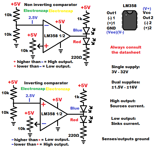
The LM358 is a well known single supply op amp.
- Non Inverting Comparator – Op Amp
- Inverting Op Amp Comparator Circuit
- Voltage Follower Op Amp Circuit
- Current Source using Op Amp
- Astable Multivibrator using an Op Amp
- Fading an LED on and off circuit using 2 Op Amps
Basic rules for comparator circuits are…
- Non inverting input with a higher voltage than the inverting input = a high output. +in > -in = Hout
- Non inverting input with a lower voltage than the inverting input = a low output. +in < -in = Lout
- Inputs just look at voltage. They don’t let current (other than a small amount of leakage) through them.
- High output means the output voltage is as close to the positive supply voltage as the output can provide, up to the maximum current that it can provide.
- Low output means that the output voltage is as close to the negative supply/ground voltage as it can provide, up to the maximum current that it can provide.
- A non inverting comparator circuit has an output that goes high when the signal voltage is higher than a reference voltage (one that doesn’t change). The signal is applied to the noninverting input (+). Whereas the reference voltage is applied to the inverting input (-).
- An inverting comparator circuit has an output that goes high when the signal voltage is lower than the reference voltage. The signal is applied to the inverting input (-). Whereas the reference voltage is applied to the non inverting input (+).
To support this site, check out the following links:
- Become a Patron!
- Check out my YouTube videos! https://www.youtube.com/c/Electronzap/videos
- Products I used in my videos or otherwise think look like a good buy. As an Amazon associate, I earn from qualifying purchases. https://www.amazon.com/shop/electronzapdotcom
- Information on this site is not guaranteed to be accurate. Always consult the manufacturer info/datasheet of parts you use. Research the proper safety precautions for everything you do.
- Electronzap is a participant in the Amazon Services LLC Associates Program, an affiliate advertising program designed to provide a means for sites to earn advertising fees by advertising and linking to amazon.com.