Table of Contents
Capacitors are similar to rechargeable batteries in that they can be charged, and then that stored charge can be used later.
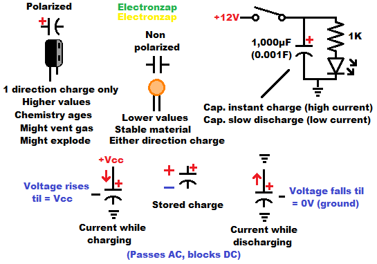
- Capacitors have 2 conductive areas called plates that are separated by a thin insulator. That inspires the schematic symbol which has 2 lines with a gap between them.
- Nonpolarized capacitor symbols have 2 straight lines indicating the plates,
- Whereas polarized capacitor schematic symbols have a curved plate on the negative side and maybe other indications of polarity, such as a plus symbol on the positive side.
- Usually it is hard to remove or add electrons from atoms, but when 2 conductive plates are close to each other, then some can be removed from one plate (becoming more positive) while at the same time the same number of electrons are added to the other plate (becoming more negative.
- An electric field forms between the atoms on one side of the gap that have given up an electron and the atoms on the other side of the plate that have gained an electron. The electric field helps hold that imbalance, but as soon as there is a conductive path for the electrons to return, they will start doing so based on the voltage built up and the total number of charges that need to move.
- Current is the moving of charges. Although we imagine a flow of positive charges moving towards negative due to misunderstanding in the early invention of circuit analysis, in reality, electrons move from negative to positive.
- A battery or other power source forces current flow to charge a capacitor until it builds up the same voltage being applied to it. And then later on, the capacitor moves the charges back towards normal while discharging.
- Larger value capacitors need more current flow to build up each volt across it compared to lower value capacitors.
- Q is used to indicate charge in formulas
- +Q = positive charge
- -Q = negative charge
Primary capacitor uses:
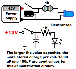
- Smoothing: Provides power during brief supply interruptions. The more capacitance there is, the longer it can provide power.
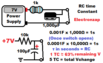
- RC timing: Capacitor voltage changes in an easy to calculate way when it is charged or discharged though a resistor.
- Voltage ramp: Steady current while charging or discharging results in a steady voltage change.
- High current: Capacitors can be discharged practically instantly. If you want a very short burst of very high voltage and current (such as simulating a lightning strike), then capacitors may work better than batteries.
Demonstration circuits:
Energy storage/smoothing:
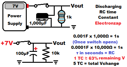
RC Time Constant:
Charging:
The closed switch in the following demonstration circuit instantly discharges the capacitor (So don’t use a value higher that probably about 1,000µF) and keeps it discharged. Opening the switch is what starts the charging process.
Discharging:
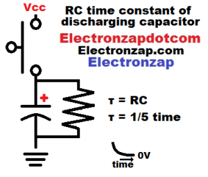
In the circuit below, the closed switch instantly (Technically, as fast as the supply can provide current) charges the capacitor to the voltage applied while also providing current for the resistor and Vout. Opening the switch starts the capacitor discharge process through the resistor as long as Vout does not need any current. If Vout needs current, that will discharge the capacitor even more quickly.
“Vout” usually indicated the input of circuitry that monitors the voltage, such as an integrated circuit input.
Voltage ramp:
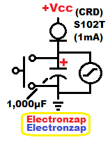
Charging a capacitor with a steady amount of current will result in a steady rise in voltage. 1A will charge a 1F capacitor at 1V per second. 1mA will charge a 1,000µF (same as 1mF) at 1V per second as well.
If a 1F super capacitor is at 0 volts, and then it is given 1A of current, it will take 5 seconds to charge it to 5V. Make sure that it is a super capacitor rated for at least 5V.
The S102T Current Regulator Diode (CRD) component provides close to 1mA of current as long as there is at least about 2 volts of voltage difference across it. It does appear to still provide quite a bit of current until it has no voltage difference across it. Other current sources didn’t do so well as the voltage gets lower across them.
How capacitors work:
Usually electrons move through a conductive circuit in a way similar to how a train would move if it was on a closed track and the whole train was connected end to end along the entire track. Every part of the track would either have no train movement at all, or it would have the same number of cars per minute moving past every other part of the track at any given time.
Electrons don’t behave exactly like that of course, but during electron flow, electrons do shuffle along conductive atoms of a conductive path, much like the train analogy given above.
When it comes to electric current, 1 Amp of current/electron flow is one coulomb (an insanely large number) of electrons moving past any particular point of a series circuit per second (1A = 1C/s). Over a period of 5 seconds, one amp of current will move 5 coulombs of electrons (1A x 5s = 5C) past any particular point of a series circuit. And so on.
Good conductors have a lone valence (outer most) electron that it does hold on to, but it can be replaced really easily with another electron as it is only being held on to by one proton that is far away from it. On the other hand, insulators have a large number of valence electrons that a relatively large number of protons are keeping locked into place pretty well.
Capacitors create a very special open circuit within a series circuit, The conductive path is interrupted by a very thin insulator. That insulator is so thin though that the atoms (protons) on one side can still pull on electrons from the other side, creating an electric field.
There is always the same total number of electrons within the capacitor component, but when charged, one plate has fewer electrons (positively charged) while the other plate has an equal number of extra electrons (negatively charged).
That electron imbalance is nowhere near permanent. The plates still want to restore balance and therefore the 2 sides of the capacitor generates a voltage until the capacitor is discharged and therefore balance is restored.
The more electron imbalance for a given capacitor, the higher the voltage that is built up across it. Very large capacitors have more plate area. They take a lot more of an imbalance (longer period of current flow) while charging to build up the same voltage as a smaller capacitor. larger capacitors also provide a lot more current while discharging before it runs out of voltage.
Once a capacitor reaches the same voltage as whatever is charging them, it doesn’t accept any more charge and is considered fully charged. Every capacitor has a voltage limit that it can be charged to, which must not be exceeded, or the capacitor is likely to be damaged.
Large value capacitors are almost always polarized. One side has to be positively charged, while the other side has to be negatively charged. Reverse charging is likely to damage it, maybe even explosively!
To support this site, check out the following links:
- Become a Patron!
- Check out my YouTube videos! https://www.youtube.com/c/Electronzap/videos
- Products I used in my videos or otherwise think look like a good buy. As an Amazon associate, I earn from qualifying purchases. https://www.amazon.com/shop/electronzapdotcom
This is a new page that will be updated soon!
- Information on this site is not guaranteed to be accurate. Always consult the manufacturer info/datasheet of parts you use. Research the proper safety precautions for everything you do.
- Electronzap is a participant in the Amazon Services LLC Associates Program, an affiliate advertising program designed to provide a means for sites to earn advertising fees by advertising and linking to amazon.com.