Table of Contents
Voltage followers take the voltage of a weak signal (input), and outputs that same voltage. The output is able to provide a lot more current at that voltage than a weak signal can. Weak signals that have to provide current, lose almost all of their voltage, and thus provide almost no power to a load.
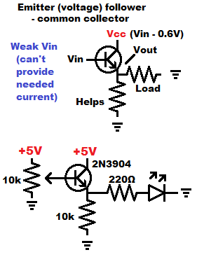
It must be kept in mind that Bipolar Junction Transistor (BJT) emitter followers have a 0.6V difference between what the signal input voltage is, and the voltage that is output.
An NPN plus a PNP BJT can be combined (cascaded) in order to get the same voltage out as in. But not all the way to either supply voltage.
NPN BJT emitter follower will output 0.6V less than the signals it is given, whereas a PNP BJT emitter follower will output 0.6V more than the signal it is given.
It’s preferred to take almost no current at all from the signal source. as it will likely drop it’s voltage if it is a weak signal. But, the BJT does actually need a little bit of current, which should still be no problem for most weak signals to provide. An op amp needs much less current from the signal than a BJT and outputs the exact same voltage, but probably can’t provide near as much current as a BJT, by itself.
The extra emitter resistor going to ground, helps ensure that the output voltage is correct. Some loads may throw it off without it. Often that resistor is 10k, but doesn’t need to be.
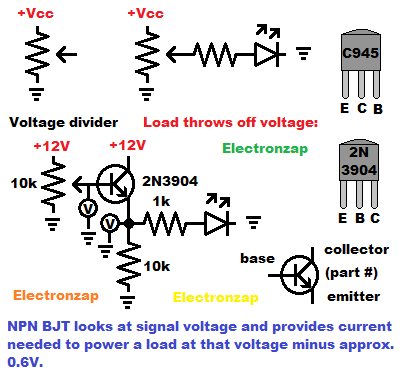
Resistance based voltage dividers can’t hold their set voltage if current is demanded of them.
Amplifying that signal with a voltage follower, such as the NPN BJT, can provide a lot more current, while maintaining the voltage divider voltage, but minus 0.6V when using a NPN BJT.
This is not free power of course.
Ultimately the output power is provided by the power source. The transistor simply controls how much of the supply voltage is applied at the output.
Video:
NPN BJT emitter follower voltage regulator using a zener diode:
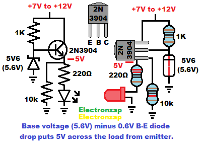
Zener diodes are another component that also produces an output voltage with limitations.
Being diodes, they need to have current limited though them. Whatever limits that current, also has to provide whatever current is needed from the output.
You would have to pick a resistor that probably works for only one load. Changing the load with just a Zener and current limiting resistor will probably require changing the resistor as well. That makes for a poor voltage regulator circuit.
A BJT makes a good voltage follower as long as you remember that there is a 0.6V difference of input versus output. NPN BJTs lower the output voltage by about 0.6V, whereas PNP BJTs raise the output voltage by about 0.6V.
5.6V is a commonly available Zener voltage. Using a 5.6V zener diode to set a NPN BJT emitter follower will result in a 5V output. A commonly desired voltage.
Video:
Cascading PNP and NPN BJTs to get the same voltage out as in:
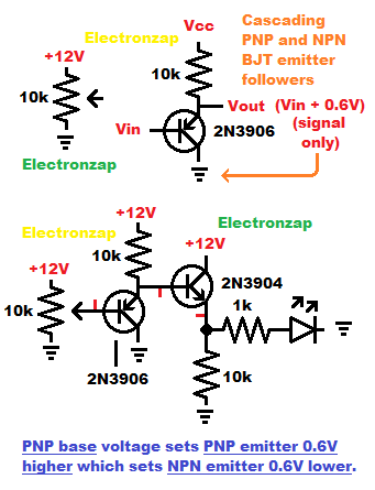
PNP BJT emitter follower outputs approx. 0.6V higher than the Base voltage. That is because it’s emitter resistor is on the high side (positive supply) of the transistor.
Since the PNP’s output current comes through a resistor from the positive supply, it can not provide much current to a load headed to ground or other more negative supply.
In direct current transistor circuits, loads are almost always powered on the high side, headed to ground. Instead of powering them on the low side, headed to the positive supply.
However, if that PNP output is used as the input of an NPN emitter follower, then the NPN output will drop that additional 0.6V gain from the PNP BJT. You will end up with the same voltage out as the voltage it, but it will fall short 0.6V of either supply voltage,
Video:
To support this site, check out the following links:
- Become a Patron!
- Check out my YouTube videos! https://www.youtube.com/c/Electronzap/videos
- Products I used in my videos or otherwise think look like a good buy. As an Amazon associate, I earn from qualifying purchases. My Amazon affiliate page showing products I think look good
- Information on this site is not guaranteed to be accurate. Always consult the manufacturer info/datasheet of parts you use. Research the proper safety precautions for everything you do.
- Electronzap is a participant in the Amazon Services LLC Associates Program, an affiliate advertising program designed to provide a means for sites to earn advertising fees by advertising and linking to amazon.com.