Table of Contents
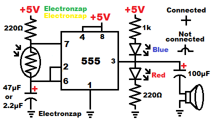
- Pins 2 (trigger) and 6 (threshold) monitor capacitor voltage.
- Less than 1/3 supply voltage to pin 2 results in a high output and a charging capacitor through the resistance from the positive supply voltage (Vcc). Pin 7 (discharge) is not connected to ground at that time, and thus it is not discharging the capacitor yet. Pin 7 is basically an open (off) switch. This is the starting point when power is first applied to the circuit.
- When pin 6 senses that the capacitor has charged to 2/3 or more of the supply voltage, then the output goes low, and pin 7 connects to ground in order to discharge the capacitor.
- The 2 steps above keep repeating for as long as there is power applied to the circuit. There is no stable output. Which is called astable.
Assorted integrated circuits (ICs) kit shown above. Included is the NE555 timers and other commonly known ICs. I have previously covered some of the other ICs in YouTube videos. An Affiliate link ad that supports this channel.
- The LEDs indicate whether the output is high (close to Vcc voltage) or low (ground/0V) as long as the frequency is low. When wired as shown, the red LED lights up when the output is high and the blue LED lights up when the output is low. It helps to visualize what a circuit output is doing when you can see flashing LEDs.
- Speaker clicks while the frequency is low. That is when the output doesn’t switch between high and low very often.
- The output capacitor pushes the speaker cone in one direction for a short period of time when the output is high, and then pulls the speaker cone in the opposite direction for a short period of time when the output is low. It easily passes alternating current, while blocking direct current. There needs to be current to move the speaker cone.
- As the frequency gets higher (output goes high and low rapidly), then both LEDs look to be on steadily because your eyes aren’t quick enough to notice when they are off for such a short period of time. The speaker goes from faster clicks to making a higher pitched tone as frequency increases.
- Bright light on the light dependent resistor (LDR) lowers the resistance that the timing capacitor both charges and discharges though. Therefore it will charge and discharge faster under bright light, and there will a high pitch tone.
- Low light on the LDR creates high resistance that the timing capacitor has to charge and discharge through. Therefore it will be a slow process, and the speaker won’t click very often if at all.
- And of course, a middle ground light level falling on the LDR will give you a number of clicks or a tone that falls between those extremes.
- The resistor from Vcc to to pin 7 and the LDR, makes sure that there is at least that much resistance while capacitor is charging while there is a very bright light on the LDR. Plus it limits how much waste current is lost when pin 7 connects to ground. It adds to the resistance of the LDR while the capacitor is charging as far as the timing is concerned.
Video:
To support this site, check out the following links:
- Become a Patron!
- Check out my YouTube videos! https://www.youtube.com/c/Electronzap/videos
- Products I used in my videos or otherwise think look like a good buy. As an Amazon associate, I earn from qualifying purchases. https://www.amazon.com/shop/electronzapdotcom
- Information on this site is not guaranteed to be accurate. Always consult the manufacturer info/datasheet of parts you use. Research the proper safety precautions for everything you do.
- Electronzap is a participant in the Amazon Services LLC Associates Program, an affiliate advertising program designed to provide a means for sites to earn advertising fees by advertising and linking to amazon.com.