Table of Contents
 After learning about the basic resistor, diode/LED and capacitor components, it is then a good time to study the 555 timer. You can quickly combine all of those components together to make fun circuits.
There are millions of 555 timer circuit schematic diagrams, which can be found by doing google searches. Once you have found a 555 timer circuit that you would like to build, all you have to do is wire the 555 component pin number as shown in the schematic.
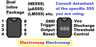
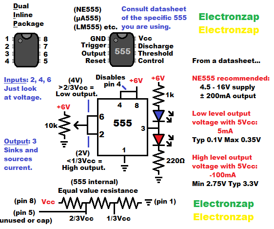
- The basic schematic symbol is a box/square.
- Part number should be located inside the IC schematic symbol box.
- If it is just showing 555, NE555, or µA555, then usually either a NE555 or µA555 should work just fine. You probably won’t come across a plain ole 555.
- If it lists a different variant, such as LM555 or LMC555, then it is likely that you need to use that exact variant or a suitable alternative. In those cases, it is probably a specialized circuit that requires some electrical properties that the original 555 doesn’t provide.
- The other numbers inside the schematic box are the pin numbers of the physical IC. The physical component has 1 or 2 indents on/near the top of it. Number 1 is the top left pin, and the numbers circle around counter clockwise. Down the left side, and then up the right side. The last number being the top right pin, which is pin 8 of a dual inline package (DIP) 555 timer.
Each variant, indicated by different letters and/or numbers in the part number, might have a large difference in capabilities compared to the base model. Those differences must be taken into consideration while designing or modifying circuits. A google search of the exact part number and “datasheet” should result in the datasheets of multiple manufacturers.
Assorted integrated circuits (ICs) kit. Included is the NE555 timers and other commonly known ICs. I have previously covered some of the other ICs in YouTube videos. It is an Affiliate link ad that supports this channel.
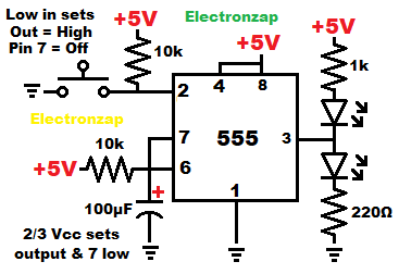
Bistable Mode/Flip Flop:
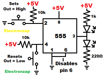
Bistable 555 output is either high (close to positive supply voltage) or low (close to ground). The state of which depends on whether the set/trigger pin (output high), or the reset pin (output low) was last triggered.
Both the trigger pin, and the reset pin, are active low. That means that they respond to a low (voltage close to 0V/ground) signal, while ignoring a higher voltage.
The circuit is called bistable because it is stable (stays) in one of two (bi) output states. It stays in that state until forced to change to the other state.
This next diagram is a modification made for the demonstration video that I made for a more recent YouTube video series.
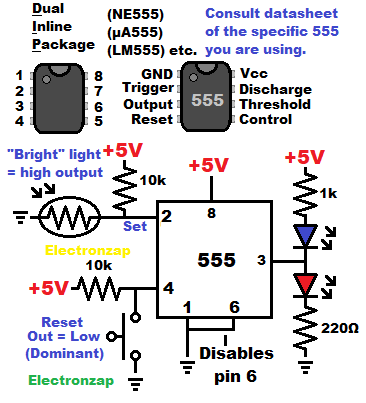
A light dependent resistor is used to switch the set pin, based on how much light is falling on the LDR. Whereas the circuit must still be reset by using the pushbutton switch connected to the reset pin.
Brighter light lowers the light dependent resistor (LDR) resistance until it drops the voltage at pin 2 (set) to below 1/3 of the supply voltage. That sets the output high. If it is already high, then it simply stays high.
Output stays high until pin 4 (reset) gets a low enough voltage by pressing the push button switch. Which connects directly to 0V ground and sets the output low again.
Even if the set pin has less than 1/3 of the supply voltage, it is overpower by the reset pin for as long as the button is pressed. If the set pin is low when the reset switch is released, then the output will jump high at that point.
The reset pin sets and/or holds the output low no matter what, as long as it receives a low signal.
Video:
Monostable Mode:
Output is low until a pulse (short low input) is given to the set/trigger pin. That pulse sets the output high for the time that it takes the capacitor at the threshold/6 pin to charge to 2/3 of the supply voltage (Vcc).
This is called Monostable because it is stable (stays) in only one state (mono) of low, until forced to change. After being forced into the high state, the monostable 555 circuit automatically sets itself back to low once the timing is done. Therefore, the high state is not stable, only the low state is.
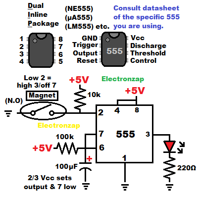
I used a magnetic switch to set the monostable mode 555 timer in my recent video series.
Video:
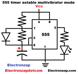
Astable Mode:
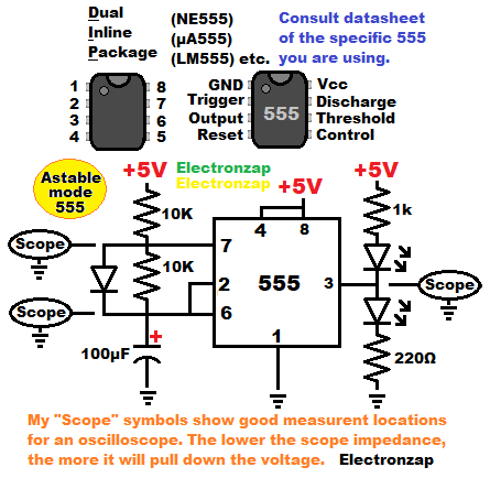
Output keeps alternating between high and low for as long as the circuit is being powered. Timing is determined by how long the capacitor takes to charge (output high) to 2/3 supply voltage, and by how the long capacitor takes to discharge (output low) to 1/3 supply voltage.
Astable means the same thing as “not stable”. There is no stable state that the output will stay in until it is forced to change. It just keeping changing output states on it’s own.
Schmitt trigger inverted digital signal:
The output is set low when the input signal gets to 2/3 Vcc (supply voltage) or higher. Whereas the output is set high when the input signal gets to 1/3 Vcc or lower. Between 1/3 and 2/3 supply voltage, the output stays in the last state that it was put into. The range of voltages where the output stays in whatever state it was last put into is called hysteresis.
- Schmitt triggers are switch circuits or inputs with hysteresis.
- Inverters (digital) are circuits that have a high output when the input signal is low, and a low output when the input signal is high. Not to be confused with power inverters, which are devices that take a DC voltage and convert it into (usually to household voltage) AC.
To support this site, check out the following links:
- Become a Patron!
- Check out my YouTube videos! https://www.youtube.com/c/Electronzap/videos
- Products I used in my videos or otherwise think look like a good buy. As an Amazon associate, I earn from qualifying purchases. https://www.amazon.com/shop/electronzapdotcom
This is a new page that will be updated soon!
- Information on this site is not guaranteed to be accurate. Always consult the manufacturer info/datasheet of parts you use. Research the proper safety precautions for everything you do.
- Electronzap is a participant in the Amazon Services LLC Associates Program, an affiliate advertising program designed to provide a means for sites to earn advertising fees by advertising and linking to amazon.com.