Table of Contents
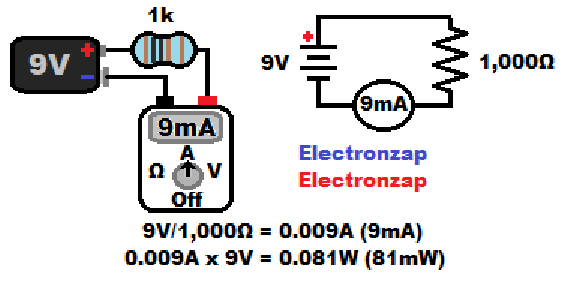
Electric current flows through series components equally. Therefore, that same current needs to flow through the meter, that is flowing through the circuit, in order for it to be measured. The circuit needs to be opened, and the meter needs to be connected in series with the circuit.

There are clamp meters that measure current by the magnetic fields it produces, but I don’t have one, and they aren’t being covered here.
Do not try to measure the current of a power source.
Meters that measure current do not limit the current while measuring it. Therefore you need to make sure that the circuit limits current enough to protect the components and the meter. Don’t try to measure current from a power source directly.
- Open the circuit. Separate (open) a connection somewhere between series components. You can also go to an open switch if there is one and it’s terminals are exposed.
- Set the meter to measure more current than you will be measuring. If you measure a higher amount of current than what it is set to, then you will likely blow a fuse in the meter. After that you will have to replace the fuse before you will be able to take that measurement again.
- Turn the meter on if it doesn’t automatically do so when you turn the dial.
- Make sure that the multimeter probes (red and black) are plugged into the correct slots for measuring the amount of current that you will be measuring. Varies a bit by multimeter.
- Black probe probably goes into a slot labeled com.
- Red probably goes into a slot that indicates mA, unless you will be measuring an amp or more.
- For measuring an amp (ampere) or more, there is probably separate slot that is labeled “A”
- Close the circuit by touching the red probe to the more positive side of the circuit, while touching the black probe to the more negative side of the circuit. Read the results on the display.
- Turn meter off when you are done.
- If there is a power button, instead of turning the dial to off, then I turn the dial to the highest voltage measuring setting so that I don’t accidently put current through the meter later on.
Schematic diagrams will sometimes show a multimeter current measurement symbol. It is a circle along a conductive path (node), with the calculated value in A/mA/µA etc. written within it.
Often times the current meter symbol is just added to show how much current you can expect that circuit to have if you measure it. It doesn’t mean that you have to add the meter to the circuit.
Video:
To support this site, check out the following links:
- Become a Patron!
- Check out my YouTube videos! https://www.youtube.com/c/Electronzap/videos
- Products I used in my videos or otherwise think look like a good buy. As an Amazon associate, I earn from qualifying purchases. https://www.amazon.com/shop/electronzapdotcom
- Information on this site is not guaranteed to be accurate. Always consult the manufacturer info/datasheet of parts you use. Research the proper safety precautions for everything you do.
- Electronzap is a participant in the Amazon Services LLC Associates Program, an affiliate advertising program designed to provide a means for sites to earn advertising fees by advertising and linking to amazon.com.