Table of Contents
Resistors are combined in order to get a number of different electrical properties than what any particular lone resistor provides.
Quick intro to the purposes of resistor combinations:
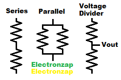
- Series resistors: Adds up resistance. They also divide voltage if you measure the voltage where they connect to each other.
- Parallel resistors: Each parallel resistor adds to the total amount of current that flows based on the voltage across them. Therefore, there is an equivalent of less resistance than any of those resistors by themselves.
- Voltage divider: Provides a signal voltage output (Vout) that is a percent/fraction of the total voltage across the series resistances. Signals are not usually meant to provide power. They are mostly just meant to give an output voltage (Vout), to the input (Vin) of some other circuitry.
Series Resistors:
The following points are a quick review of the basic resistor properties to keep in mind while comparing the single resistor circuits to the series resistors circuits in the diagram below.
- Current (I) in amps, is the voltage (V) across a resistor, divided by it’s resistance in ohms (Ω). I = V/R
- Power in watts (W) is the voltage across a resistor times the current (I) in amps flowing through the resistor. P = VI
- Current for most electronic circuits is usually less than an amp. Therefore current values are typically communicated in milliamps (mA). 1mA is the same as 0.001A. Remember that formulas are calculated in amps.
- Most resistors are rated for 1/4W (0.25W). But it’s still best to keep them below 1/8W (0.125). You also need to have them exposed to room temperature air.
Written explanations of the diagram examples.
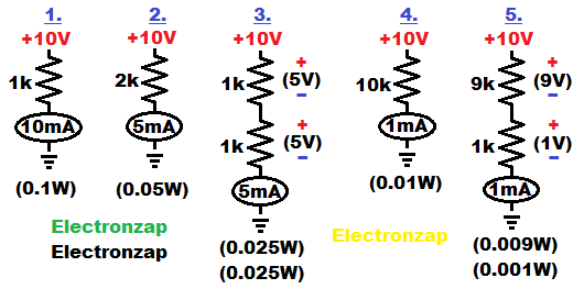
- The 1,000Ω (1k) resistor allows 1mA of current through it, per volt across it. 10V/1,000Ω = 0.01A (10mA) of current. The heat generated is 10V x 0.01A = 0.1W (100mW) of power. Which must be dissipated by the resistor.
- A single 2,000Ω (2k) resistor allows 0.5mA (0.0005A) of current through it per volt across it. Therefore 10V/2000Ω = 0.005A (5mA). That creates 10V x 0.005A = 0.05W of power (heat) that must be dissipated.
- Combining two 1,000Ω resistors in series adds their resistances up. 1,000Ω + 1,000Ω = 2,000Ω. Therefor you will have an equivalent of 2,000 ohms of resistance as far as the current that will pass through the circuit is concerned. For the 10V supply example above… 10V/2000Ω = 0.005A (5mA).
- Being two equal value resistors connected in series, each resistor will have half of the total supply voltage across them. 5V/1,000Ω = 0.005A through each resistor. They divide the voltage based on their percentage of the total resistance.
- The heat generated by each resistor in this case is 5V x 0.005A = 0.025W (25mW). Therefore, each of the two series 1k resistors gets half as hot as a single 2k resistor would have gotten if it was used instead.
- A 10,000Ω (10k) resistor with 10V across it will allow 10V/10,000Ω = 0.001A (1mA) of current to pass through it. It will generate 10V x 0.001A = 0.01W (10mW) of power to dissipate.
- By combining a 9,000Ω and a 1,000Ω resistor in series, you will have an equivalent of 10,000 ohms of resistance when it comes to how much current will flow through the circuit. 10V/10,000Ω = 0.001A (1mA).
- Since 90% of the total series resistance is the 9k resistor, it will have 90% of the supply voltage across it. Whereas the 10k resistor will only have 10% of the supply voltage across it because it is 10% of the total series resistance.
- That also means the 9k resistor will generate 9 times as much heat (9V x 0.001A = 0.009W) as the 1k resistor (1V x 0.001A = 0.001W) in series with it. It is safe to put a very low value resistor in series with a higher value resistor, because the higher value series resistor absorbs most of the power.
Keep in mind, that resistor are often connected in series in order to get an equivalent value that you don’t already have in your assortment of resistors laying around.
Resistors can also be connected in series to spread out the power dissipation. So, although learning about power dissipation can be confusing at first, once you understand it, it will make designing your own circuits and understanding other people’s circuits a whole lot easier.
Parallel Resistors:
Parallel resistors simply add up how much total current is passed through them based on the voltage across them. Since parallel resistors allow more total current to flow than any of the resistors alone, they always have an equivalent of less resistance than any of the resistors would have provided by itself.
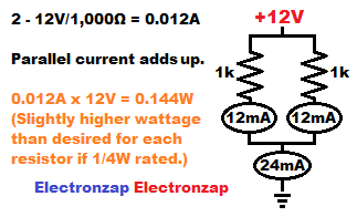
For example, lets look at 12V across two 1,000Ω (1k) resistors. (See diagram).
- 12V/1,000Ω = 0.012A (usually referred to 12mA) is the circuit current through a lone 1,000 ohm resistor being powered by 12V.
- If there is 12mA of current flowing through each of two parallel resistors, then wherever those 2 current paths come together into a single conductive path, the current becomes 12mA + 12mA = 24mA of total current.
- The 12V power supply in our example circuit, has to provide a total of 24mA of current to power our two parallel 1,000Ω resistors. So as far as it is concerned, it is powering a load of 12V/0.024A = 500Ω of equivalent resistance.
Protecting an LED from a relatively high voltage:
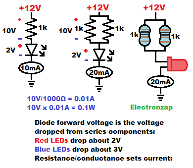
In this diagram, I show a better way to protect an LED from relatively high voltage by using parallel 1/4W resistors over a single 1/4W resistor. We should do so if we want to protect an LED from 12V while still getting close to the LED’s maximum recommended current of 20mA through it. Most resistors are only rated for 1/4W (0.25W maximum – 0.125W recommended) and there’s no point of having to buy higher wattage resistor when there is a simpler alternative.
A lone 500Ω ohm resistor protecting a 2 Vf (Two volt forward voltage) LED from 12V will have 10V across the resistor and therefore will pass 10V/500Ω = 0.02A (usually referred to as 20mA) of current through both it and the series LED. That means that the resistor will have to dissipate 10V x 0.02A = 0.2W of power. That doesn’t exceed it’s maximum wattage if it is a 0.25W resistor, but it is still higher than desired. It can even be dangerous if there is not enough exposure to room temperature air or other cooling sources.
- A lone 1,000Ω resistor protecting a 2V forward voltage (2Vf) LED from 12V will pass 10V/1,000Ω = 0.01A of current, and the resistor will have to dissipate 10V x 0.01A = 0.1W of power.
- Two 1,000Ω resistor connected in parallel with each other, but in series with a single 2Vf LED, and being powered by a 12V supply, will each pass 0.01A. Those two separate 10mA currents through the resistors will combine together for a total of 20mA total through the LED.
- Keep in mind that the LED becomes a pretty good conductor after it has dropped it’s forward voltage. It doesn’t really limit current once it’s forward voltage is exceeded.
- The power dissipation of each resistors will still be 10V x 01A = 0.1W . Therefore, neither parallel 1k resistor gets near as hot as a single 500Ω resistor used in their place in orer to provide the same current.
Voltage Divider:
Coming soon!
To support this site, check out the following links:
- Become a Patron!
- Check out my YouTube videos! https://www.youtube.com/c/Electronzap/videos
- Products I used in my videos or otherwise think look like a good buy. As an Amazon associate, I earn from qualifying purchases. https://www.amazon.com/shop/electronzapdotcom
This is a new page that will be updated soon!
- Information on this site is not guaranteed to be accurate. Always consult the manufacturer info/datasheet of parts you use. Research the proper safety precautions for everything you do.
- Electronzap is a participant in the Amazon Services LLC Associates Program, an affiliate advertising program designed to provide a means for sites to earn advertising fees by advertising and linking to amazon.com.