Table of Contents
Common symbols:
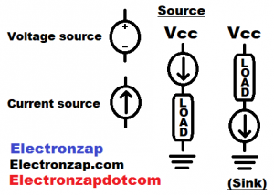
There are a number of ways to show voltage sources. Most of them shown in later diagrams.
- Plus and minus symbols. Usually also includes the suggested/required voltage written between the + and – symbols.
- Battery symbol (alternating short and long lines, shown in the next diagram). Usually 2 pairs of lines, with a voltage written next to it. Sometimes there is one short and long line for each individual cell. That helps better show how the cells are connected in series and/or parallel.
- Vcc may be used to indicate where the positive side of the power supply is connected, if there is not a recommended voltage shown. Primarily seen in Bipolar Junction Transistor (BJT) circuit schematic diagrams. But, you may see Vcc used in any type of circuit schematic.
- +V (+5V, +10V, etc.) is a common to show the positive voltage in relationship to ground.
- -V (-5V, -10V, etc.) is a common way to show the negative supply voltage in relationship to ground. Typically used it dual/split supply circuits.
A current source sets a current through it. It drops the supply voltage needed to make sure that amount of current flows through it and anything in series with it.
- Current source symbol is usually a circled arrow. The amount of current it sets is usually written next to it.
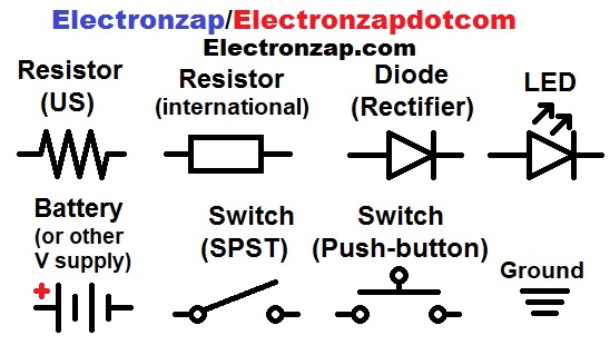
Most of the symbols in this diagram, will be seen in almost every schematic. They are commonly used components.
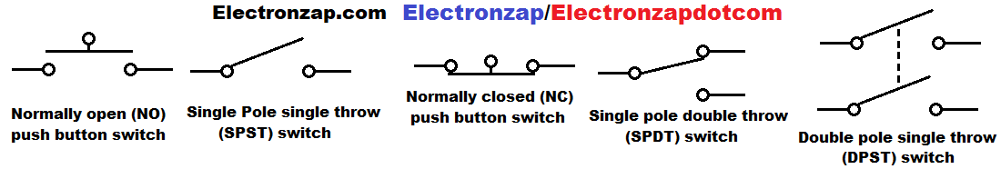
The diagram below shows a number of switch variations. You may or may not see any of them in circuits. But, they should be pretty easy to identify, as they illustrate how the switch makes a connection pretty nicely.
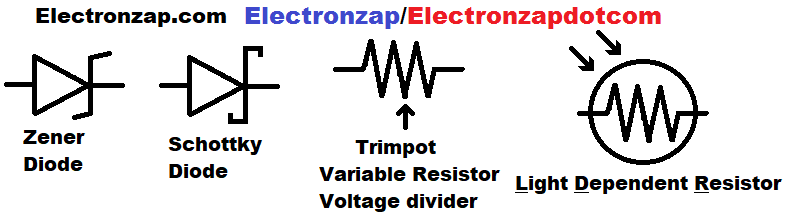
Some variations of diodes and resistors are shown below.
Common transistors are shown below. BUT, the JFET and MOSFET symbols will usually look very different in schematic diagrams. There is no universal symbol for them, the person drawing the schematic uses the symbol they like best. Pins probably won’t be labeled either.
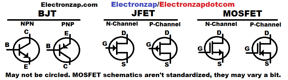
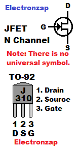
You will usually need to check the particular transistor’s datasheet for it’s pin layout. It varies, depending on part number and package (what it looks like).
- C = collector:
- B = Base:
- E = Emitter:
- D = Drain:
- G = Gate:
- S = Source:
Resistor:
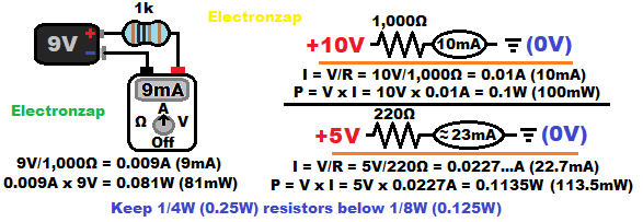
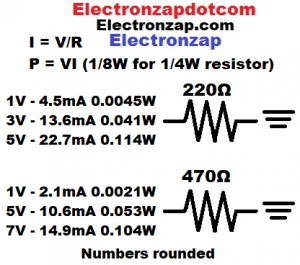
Resistors limit the amount of current (I) flowing through them, based in the voltage across them, and their resistance. Ohms law for current is I = V/R
Heat (power) is produced as a resistor limits current. The more voltage that is across a components, and the more current (I) forced through a components, the hotter it gets. P = V x I
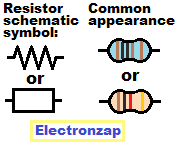
Jagged lines are usually used to indicate a resistor, or resistive component/load. But, a rectangle is sometimes used.
Resistor values:
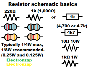
A recommended resistance is usually written next to the jagged line version of the resistor component schematic, or written inside of the rectangle version.
It is usually assumed that a 1/4W (0.25W) will be used. Therefore the wattage is not usually indicated unless a higher wattage should be used.
Most resistors in kits are 1/4W. Higher wattage resistors are physically larger and often look very different. They also usually have their resistance, and possible wattage, written on them.
Measuring current through a meter:
Current is the same throughout series components. It is therefore usually measured by opening up the circuit, setting the meter to measure more current than is expected, and then closing that opening by connecting the probes to both ends. Red probe to the more positive side, and black probe to the more negative side.
There are also clamp meters (not shown here), which measure current by detecting how much electromagnetic field there is around the wire being measured. More current = a stronger electromagnetic field.
You don’t always have to put a meter in a spot that shows one on a schematic diagram. It is often just one way to show the current of a circuit.
Diode/LED (Light Emitting Diode):
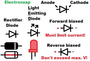
Diodes, including LEDs (Light Emitting Diodes), conduct current easily in one direction, but not the other.
It is therefore important to connect the diode/LED in the proper direction. On the diode schematic symbol, The cathode is indicated by the line that the arrow part of the symbol is pointing at. LEDs have some arrows pointing away from the components symbol to indicate that it is emitting light.
For physical components, there is usually a black or gray band on the cathode side for diodes. For LEDs, there is usually a shorter lead (if they are untrimmed) and possibly a flat edge on the cathode side.
LED protected with resistor:
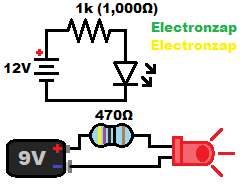
The protective resistor limits current through the LED, itself, and the battery based on the battery voltage minus the LED forward voltage.
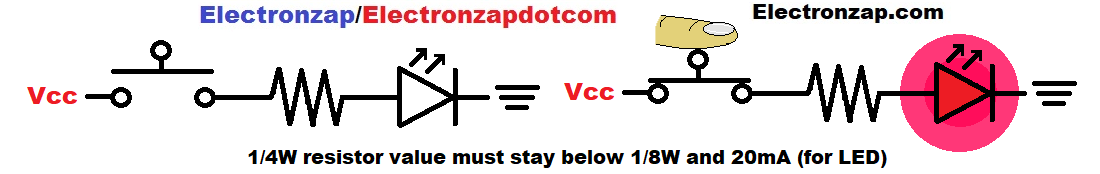
The resistor values shown are a good minimum to use for that particular voltage. It keeps the current below 20mA (for the LED), and it keeps the resistor wattage below 1/8th of a watt, which is recommended for a 1/4 watt resistor.
You can always go higher in resistance than what is shown on the schematic when the resistor is being used to limit current. The LED in this case will just be less bright due to less current.
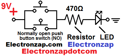
Mechanical push button switch controlled LED on/off:
Voltage meter measurement placement:
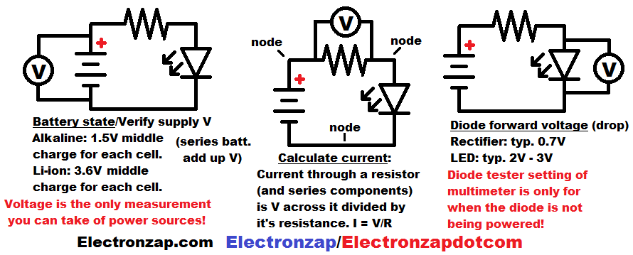
You can tell a lot about a circuit by taking voltage measurements.
- Supply/total voltage: How charged a battery is.
- Voltage across resistor: Sets the amount of current.
- Voltage across LED: Shows the amount of voltage dropped from the current setting resistor.
Voltages across components illustrated:
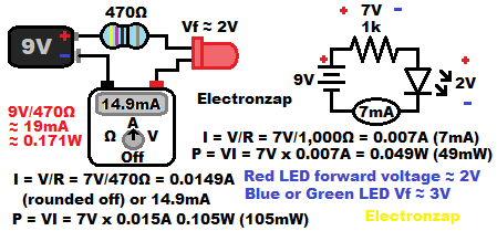
The schematic diagram in the illustration has the additional labeling of the approximate voltages you will find across both the resistor and the LED. You will sometimes notice notations like this in learning basic electronics material that is explaining voltages.
You can (and should) measure these, and all other voltages that are explained to you. Simply set the meter to measure more voltage than you can expect. Then place the red probe where the plus symbol is shown, and the black probe is placed where the negative symbol is.
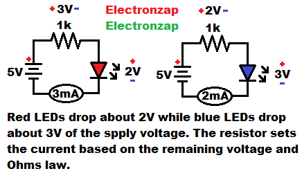
- Typically, red LEDs have a forward voltage of 2V. That voltage is subtracted from the supply voltage when it comes to how much voltage goes across the resistor, which is what sets the current. No matter the value of the resistor, it will have about 7V across it when it is protecting a red LED from 9V.
- Vf is an abbreviation for “forward voltage”.
Parallel LEDs:
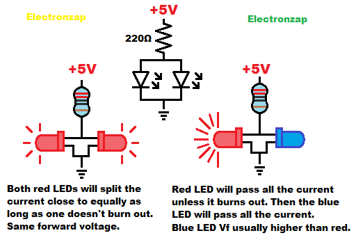
Parallel LEDs with the same forward voltage split up circuit current without affecting how much current there is.
- One red LED will drop about 2V from a current setting resistor:
- Two parallel red LEDs will still only drop about 2V from the current setting resistor . The same current will flow through the resistor as if it was setting the current for one LED, but each of the parallel LEDs will split that amount of current through them.
- A red LED doesn’t limit current once there is about 2V across it. So the voltage does not rise higher than that. The rest of the voltage is passed along to any series component(s). A Blue LED needs about 3V to conduct. So, if a blue LED is connected parallel to a red LED, it will not have enough voltage across it to conduct. The red LED will pass all of the current.
It’s best not to parallel LEDs at all. If one burns out, then the current it was passing goes through the other one(s). If they can’t handle that extra current, then they will burn out quicker.
Common resistor combinations:
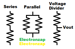
- Series resistors add up resistance and divide up voltage/power (waste heat).
- Parallel resistor have an equivalent of less resistance, by providing more total current than one of them alone. They also divide the total current, and thus power (waste heat) generation.
- Voltage divider is typically 2 series resistances with an electrical connection (output) between them that gives a fraction of the full voltage across the 2 resistances.
Series resistors:
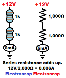
Putting two 1,000Ω resistors in series will give you an equivalent of 2,000 ohms of resistance. Series resistance simply adds up to a total resistance.
Putting 12V across 2,000Ω of resistance will result in 0.006A (6mA) of current.
The only way for a 1,000 ohm resistor to pass 6mA of current is if… 0.006A x 1,000Ω = 6V is across it. That is half of the 12V supply voltage in this case.
- 2 equal value series resistors will each have half of the supply voltage across them. The voltage across each series resistor will be the same percentage of the supply voltage as it’s percentage of series resistance. That’s how voltage is divided with resistance.
Series resistance voltage and wattage division:
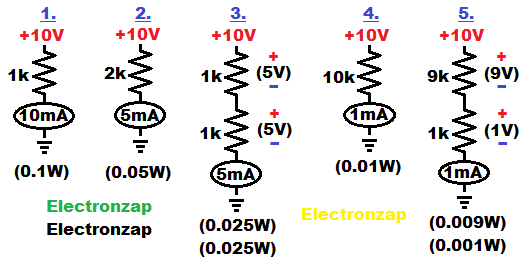
A series 9,000Ω and 1,000Ω resistors have the equivalent of 10,000Ω of resistance. Putting 10V across the two of them in series will give you 10V/10,000Ω = 0.001A (1mA) of current. You need 9V across a 9k resistor to get 1mA, and you need 1V across a 1k resistor to get 1mA of current. So that’s how the supply voltage is divided across them.
Voltage is divided across each resistor based on it’s percentage of the total resistance. That’s how they pass the same amount of current. Series components always pass the same amount of current.
Parallel resistors:
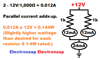
Current passes through parallel components independently based on the voltage across them. That means that if two 1,000 ohm resistors are connected in parallel, and have 12V across them, they will each pass 0.012A (12mA) of current. When those 2 currents combine, there will be 0.012A times 2 resistors = 0.024A total current. Usually referred to as 24mA.
Since the 12V power supply has to provide a total of 24mA of current through 2 parallel 1,000Ω resistors, that means that they have an equivalent of 12V/0.024A = 500Ω of resistance.
Series LEDs voltage drops:
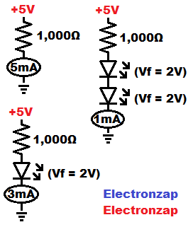
A 1,000Ω (1k) resistor passes 1 milliamp (1mA) of current through it, for every volt across it. Putting 5 volts across it results in 5mA of current through it.
By adding a series LED to the resistor, the 5V will be across both of them. The LED will drop 2V of those volts from the resistor if it has a forward voltage of 2 volts. That leaves 3 volts across the resistor, which passes 3mA through it and the series LED. LED’s don’t limit current, they just drop voltage.
A second series LED with a forward voltage of 2V will drop another 2V from the resistor, for a total of 4 volts dropped from the resistor. Since the resistor now has 5V – 4V = 1V across it, there will be 1mA of current flowing through it and the 2 series LEDs.

Never use a 220Ω to protect a single LED from 12 volts. Both components will overheat. Instead, you can keep putting LEDs in series so that they drop most of the voltage from the low value resistor. For a 12V supply, 3 LEDs will work well if they have a 3V forward voltage, and 4 LEDs will work well if they have a 2V forward voltage. Those forward voltage drops add up.
Mechanical switch based sink or source voltage to LEDs
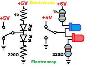
Whichever supply that the switch connects directly to, will eliminate any current to the resistor and LED headed to that same supply voltage, while giving the full supply voltage difference to the resistor and LED headed to the opposite supply voltage.
- No current LED = off
- Full current LED = on
This is basically how integrated circuit outputs can source (connected to positive) or sink (connected to negative). However they do so through transistors, which always limits voltage and/or current much more so than a mechanical switch.
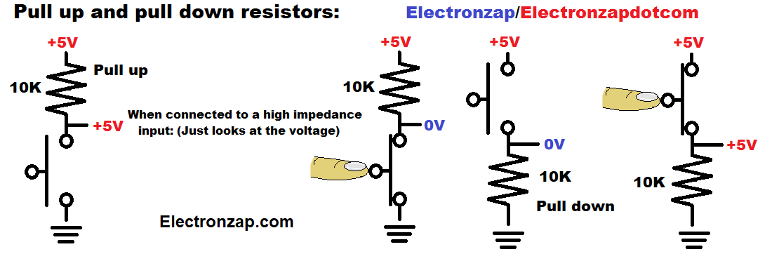
Pull up and pull down resistor:
Digital circuit inputs respond to whether a signal voltage is either near the positive supply voltage (high) or the negative supply voltage (low). Those inputs of often sensitive enough to pick up stray electromagnetic energy that will generate changing voltages unless they have a more direct connection to a specific voltage.
Switch based AND gate:
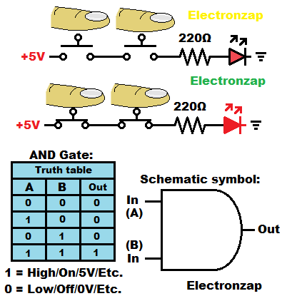
With multiple switches connected in series with a resistor and LED, all switches have to be closed (on) in order to turn the LED on.
If you see an AND gate schematic symbol on a schematic diagram, it probably refers to a digital AND gate that is built into an integrated circuit.
Usually the recommended part number of the IC is given inside the symbol. Some examples are
- 74HC08
- 4081 – CD4081
Which have 4 (quad) logic gates built into them. Check their datasheets for more information by doing a google search of ::part number:: datasheet.
Switch based OR gate:
Light dependent resistor (LDR) controlling LED brightness:
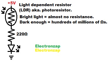
The series 220Ω fixed resistor makes sure that the LED has at least 220Ω from 5V if a very bright light falls on the photoresistor/light dependent resistor (LDR)
Light dependent/photo resistor and fixed resistor voltage dividers:
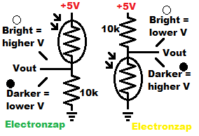
If the LDR is on the high side of the voltage divider, that means bright light will make the output connect to the positive supply better. Therefore the output voltage will rise as brighter light falls on the LDR.
If the LDR is on the low side of the voltage divider, that means bright light will make the output connect better to the negative supply/ground better. Therefore output voltage will go down as brighter light falls on the LDR.
Setting Light Dependent Resistor (LDR) upper and lower limits:
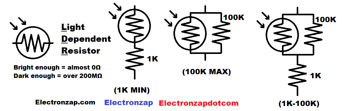
- If you put a 1,000Ω resistor in series with a LDR, then you will always have at least 1,000Ω of resistance. Even if a light were bright enough to get the LDR to 0Ω.
- Putting a 100,000Ω resistor parallel to a LDR will mean that no matter how much resistance the LDR provides, current can also go through the 100,000Ω resistor. Therefor, the will always be an equivalent of no more than 100,000Ω of resistance, no matter how little light falls on the LDR.
- You can also do a series and parallel combination with an LDR. Using the same values as above, the total resistance will be somewhere between 1,000 and 100,000, depending on how much light is falls on the LDR.
Photodiode:
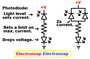
Reverse biased (RB) photodiodes let a certain amount of current flow through them based on how much light is falling on them. It doesn’t matter how much voltage is powering the circuit, the current will be he same for a given light as long as there is enough supply voltage to provide that much current/power for the rest of the load.
Two parallel RB photodiodes will allow twice as much current to flow through as a single RB photodiode when exposed to the same amount of light.
A photodiode under a bright light will allow more current to flow than is recommended for an indicator LED. A minimum value fixed resistor based on the supply voltage, connected in series with the photodiode and LED, will set the maximum current that can flow while protecting an LED from a given voltage. The photodiode(s) will just set the limit of current below that when the light isn’t as bright.
Capacitor component:
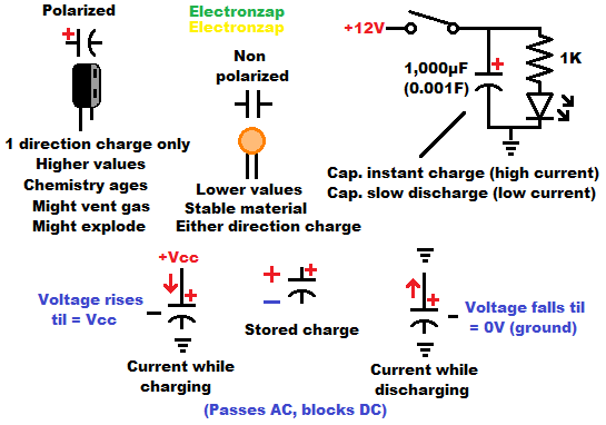
(Smoothing) capacitor energy storage demonstration:
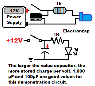
Capacitor charging through a resistor:
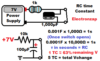
Capacitor discharging through resistor:
Voltage ramp: capacitor charged by current source
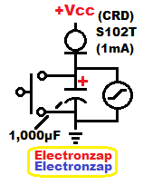
CRD = Current Regulating Diode
Series capacitors:
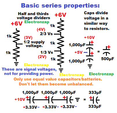
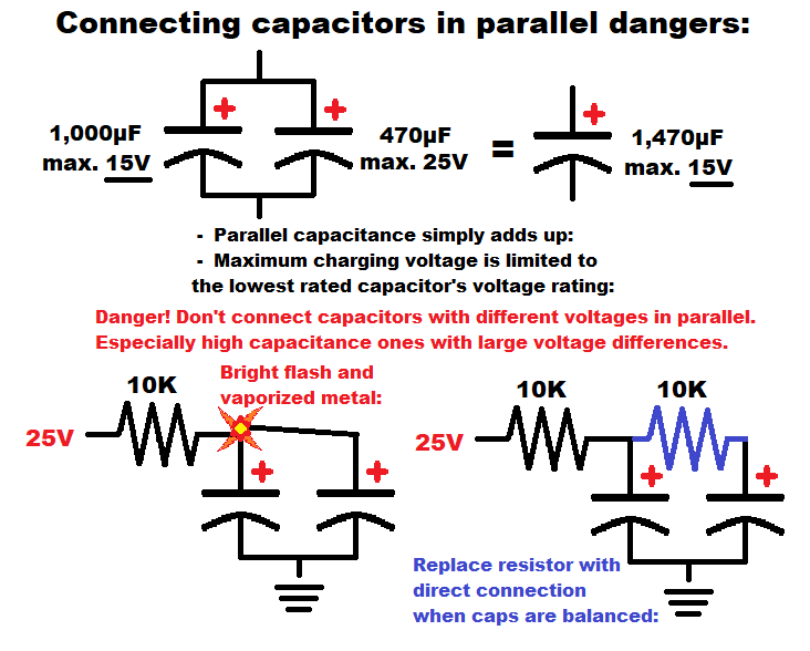
Parallel capacitors:
Battery: (To be added)
- Cell
- Battery (2 cell generic symbol)
- Actual number of cells symbol. Probably lists the chemistry, so you know what those voltages will add up to when fully charge to fully discharged.
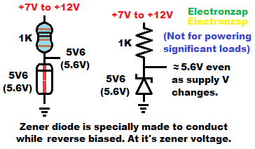
Zener diode current set by current limiting resistor:
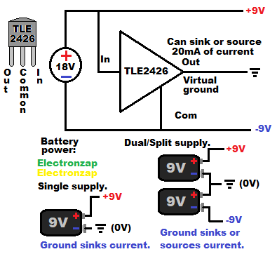
TLE2426 3 terminal rail splitter:
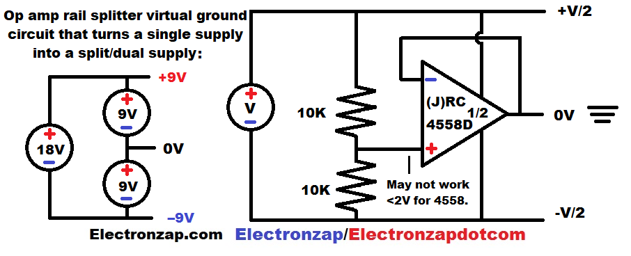
Operational amplifier rail splitter:
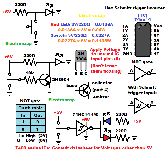
Various NOT gates (digital inverter):
N channel enhancement mode MOSFET:
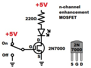
- Drain (D)
- Gate (G)
- Source (S)
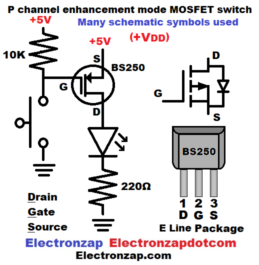
P channel enhancement mode MOSFET:
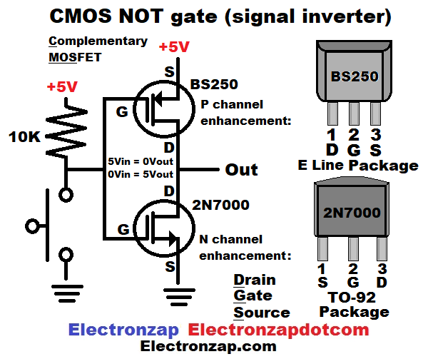
CMOS NOT gate (digital inverter):
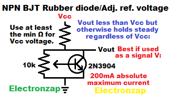
NPN BJT rubber diode:
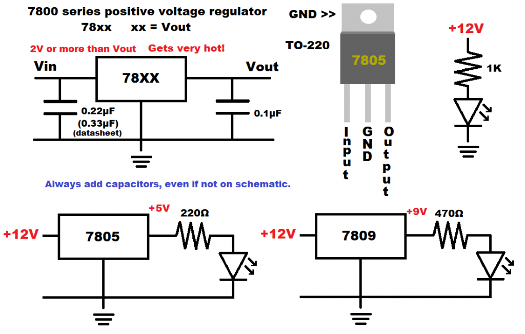
Voltage regulator:
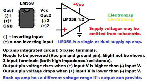
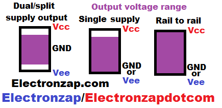
Op amp basics:
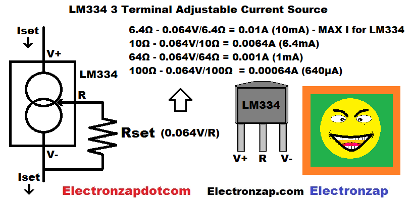
LM334 adjustable current source component:
Additional notes:
You’re goals while reading schematics should be to…
- Recognize simple circuits (fragments) within more complex circuits
- Trouble shooting
- Parts of circuits will have certain voltage patterns
- Trouble shooting
- Be able to modify/combine circuits
-
- Power needs: Type of supply. If battery: Chemistry, number of them connected in series/parallel, etc. Usually left up to you to figure out.
- Substituting components in the diagram for ones that you already have:
-
- Understand additional text (notes) that help explain the schematic.
Topics to be added…
- Single components
- Simple circuits
- Pull up/down resistors
- Battery layout (2S 2P = two series cells, two parallel cells, etc.)
- Multimeter/oscilloscope measurements
- R = Resistor, C = capacitor etc. R1, R2 etc. = Clarifies specific resistors. LED 1, will have a different voltage in relationship to ground at it’s anode than will have LED 2′ anode in series with it.
- Simple circuits
- Series
- Resistor
- Diode
- Capacitor
- Parallel
- Resistor
- Diode
- Capacitor
- 555 timer: Letters/numbers added at the beginning of the part number typically represent that there are altered electrical properties from the standard component. Letters/numbers added after the part number usually indicates enhanced properties. consult datasheet for differences
- 555 timer circuits
- Bipolar Junction Transistors (BJTs): Part number indicates electrical properties/package. Use the number shown or an equivalent. Added letter at the end of the part number often indicated an enhanced version. Common packages are TO-92, TO-220, and the not so commonly available, but shown in many datasheets is the TO-18 (metal can).
-
- 2N2222 = 600mA (NPN BJT in TO-92 package)
- 2N3904 = 200mA (NPN BJT in TO-92 package)
- 2N3906 = 200mA or -200mA (PNP BJT in TO-92 package)
- BJT circuit examples
-
- FETs
- Voltage regulator
To support this site, check out the following links:
Assorted integrated circuits (ICs) kit. It is an Affiliate link ad that supports this channel.
- Become a Patron!
- Check out my YouTube videos! https://www.youtube.com/c/Electronzap/videos
- Products I used in my videos or otherwise think look like a good buy. As an Amazon associate, I earn from qualifying purchases. https://www.amazon.com/shop/electronzapdotcom
- Information on this site is not guaranteed to be accurate. Always consult the manufacturer info/datasheet of parts you use. Research the proper safety precautions for everything you do.
- Electronzap is a participant in the Amazon Services LLC Associates Program, an affiliate advertising program designed to provide a means for sites to earn advertising fees by advertising and linking to amazon.com.