Table of Contents
Zener diodes can be used to limit a voltage across a load.
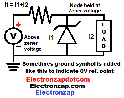
- Reverse biased Zener diode passes current when the source voltage is greater than it’s zener voltage. That current flow stops the voltage across the zener diode from getting higher than the zener voltage.
- A load parallel to the zener diode will also only have the zener voltage across it even though the supply voltage is higher. Parallel components always have the same voltage across them.
- Both the current through the zener diode, and the load, have to pass through the current limiting resistor. Therefore, the resistor has to be low enough in resistance to pass the current that the load needs, and the zener diode needs to regulate the voltage.
- Capital i (which looks like the lower case L in some fonts), is the symbol for current when doing calculations.
Kit has zener diodes and a lot of other semiconductors. An affiliate link ad that supports this site.
Video:
Brief Circuit Schematics with Short Video List of Pages
To support this site, check out the following links:
- Become a Patron!
- Check out my YouTube videos! https://www.youtube.com/c/Electronzap/videos
- Products I used in my videos or otherwise think look like a good buy. As an Amazon associate, I earn from qualifying purchases. https://www.amazon.com/shop/electronzapdotcom
- Information on this site is not guaranteed to be accurate. Always consult the manufacturer info/datasheet of parts you use. Research the proper safety precautions for everything you do.
- Electronzap is a participant in the Amazon Services LLC Associates Program, an affiliate advertising program designed to provide a means for sites to earn advertising fees by advertising and linking to amazon.com.