Table of Contents
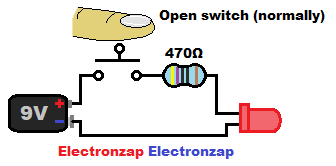
Current can’t flow while a switch is open. An opening is a non conductive gap.
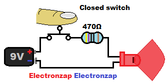
Closing the switch brings the conductive metal contacts together, so that current can flow freely through the switch. The rest of the circuit will limit the current.
Video:
LED and protective resistor review:
The switch part of the circuit above is pretty straight forward. All the switch does is either connect the load (resistor and LED) to the battery, or not. While the switch is closed…
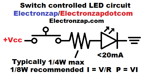
- Basic rules for the LED:
- Most LEDs should never have more than 20 milliamps (mA) of current flowing through them. LEDs do drop some voltage, but they do not limit current once their forward voltage is exceeded.
- The Anode (long lead/wire if untrimmed) needs to be connected towards the positive side of the power supply, while the Anode is connected to the negative side of the supply. That makes the LED Forward biased. Anode more negative while the cathode is more positive is called reverse biased. No current will flow while LED is reversed biased and it will not light up. Too much voltage will however destroy the LED while reverse biased. My LEDs do fine at 9V across them while RB, but burn out if the voltage is a bit higher than that.
- Basic rules for the resistor:
- Most resistors are rated for 1/4W (0.25W). So it is assumed that will be what wattage resistor is being used. Using a higher wattage resistor is never a problem, they are simply larger and cost more, so it’s best to use them only when you need them.
- Wattage is voltage times current. Therefore you need to multiply the voltage across the resistor in Volts, times the current in amps, flowing through the resistor. That gives you the power/heat (wattage) that it will have to dissipate. Try to keep a 0.25W resistor below 0.125W and exposed to room temperature air in order to keep it from overheating.
- The resistor that you use must limit current to a safe level for all the components in the circuit. Primarily the LED and resistor in this circuit since they can handle the least amount of current. But, higher power circuits may need resistance added to protect switches, power sources and any other part of a circuit. Therefore it is important to know every component’s power limit.
- Most resistors are rated for 1/4W (0.25W). So it is assumed that will be what wattage resistor is being used. Using a higher wattage resistor is never a problem, they are simply larger and cost more, so it’s best to use them only when you need them.
- LED drops it’s forward voltage from the resistor when the switch is closed.
- Once the LED drops voltage from the resistor, the remaining supply voltage is across the resistor in this circuit. That voltage in volts, divided by the resistor’s resistance in Ohms, is what sets the circuit through the entire circuit.
- Calculations for this circuit (when the switch is closed):
-
- 9V – 2V (red LED voltage drop) = 7V across the current setting/protective resistor
- 7V/470Ω = 0.015A (15mA). Which is rounded off.
- 7V times 0.015A = 0.105W.
-
To support this site, check out the following links:
- Become a Patron!
- Check out my YouTube videos! https://www.youtube.com/c/Electronzap/videos
- Products I used in my videos or otherwise think look like a good buy. As an Amazon associate, I earn from qualifying purchases. https://www.amazon.com/shop/electronzapdotcom
- Information on this site is not guaranteed to be accurate. Always consult the manufacturer info/datasheet of parts you use. Research the proper safety precautions for everything you do.
- Electronzap is a participant in the Amazon Services LLC Associates Program, an affiliate advertising program designed to provide a means for sites to earn advertising fees by advertising and linking to amazon.com.