Table of Contents
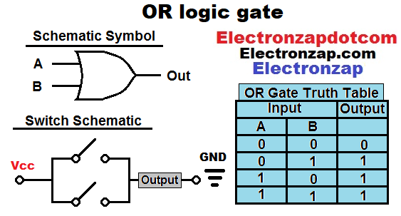
OR logic gates have a high output if at least one input is high. All inputs have to stay low for a low output.
Logic gate kit. Affiliate link ad.
If switches are connected in parallel, then turning one or more of them on, will also turn on a series load. The load is only off if all of the parallel switches are off.
Truth table:
- 1 can mean on for mechanical switch based circuits and loads. For transistors or integrated circuits (IC) based digital signals and outputs, 1 tends to mean high, or 5V if that is the voltage that is being used.
- 0 can mean off for mechanical switch based circuits and loads. For transistors or integrated circuits (IC) digital signals and output, 0 tends to mean low, or 0V if that is the most negative voltage of the circuit.
Video:
Related pages:
- Brief NPN BJT OR Logic Gate Circuit 2N3904 Bipolar Junction Transistors
- Brief 74HC32 quad 2 input OR gate demonstration Push Button Switch and Light Dependent Resistor LDR signals
To support this site, check out the following links:
Art of electronics is easily my favorite learning electronics book. It helps to already be familiar with basic electronics while studying it. It inspires many of my demonstration circuits. An affiliate link ad that supports this site.
- Become a Patron!
- Check out my YouTube videos! https://www.youtube.com/c/Electronzap/videos
- Products I used in my videos or otherwise think look like a good buy. As an Amazon associate, I earn from qualifying purchases. https://www.amazon.com/shop/electronzapdotcom
- Information on this site is not guaranteed to be accurate. Always consult the manufacturer info/datasheet of parts you use. Research the proper safety precautions for everything you do.
- Electronzap is a participant in the Amazon Services LLC Associates Program, an affiliate advertising program designed to provide a means for sites to earn advertising fees by advertising and linking to amazon.com.