Table of Contents
AND logic gates require that all inputs are high/on in order for the output to be high/on.
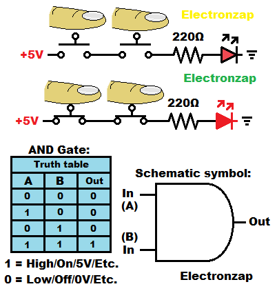
If at least one input is low/off, then the output is off.
- Closed switch = on.
- Open switch = off.
This is a really easy logic gate to make with mechanical switches for demonstration purposes. Practical circuits will most likely use an AND gate integrated circuit.
Current is the same through all series components. So, if no current can flow through one part of the circuit, then it can’t flow through any other part of the series circuit.
If all of the series switches are closed, then current can flow through them freely and the load will have the full voltage across it. The load and the supply voltage will be what sets the current through all series components while all series switches are closed.
Video:
To support this site, check out the following links:
Affiliate link ad of the portable power supply used in my videos. There are larger ones that are cheaper if portability isn’t important. I primarily got this one because I can easily film it next to my circuits while making my YouTube videos.
- Become a Patron!
- Check out my YouTube videos! https://www.youtube.com/c/Electronzap/videos
- Products I used in my videos or otherwise think look like a good buy. As an Amazon associate, I earn from qualifying purchases. https://www.amazon.com/shop/electronzapdotcom
This is a new page that will be updated soon!
- Information on this site is not guaranteed to be accurate. Always consult the manufacturer info/datasheet of parts you use. Research the proper safety precautions for everything you do.
- Electronzap is a participant in the Amazon Services LLC Associates Program, an affiliate advertising program designed to provide a means for sites to earn advertising fees by advertising and linking to amazon.com.