Table of Contents
Pull up resistor keeps the PNP BJT transistor off when the NPN BJT is off in this circuit.
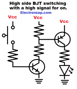
Closing the switch, turns the NPN BJT on, which connects the base of the PNP BJT to ground through a current limiting resistor. Turning on the PNP BJT.
The resistor connecting the PNP Base to NPN Collector limits current when both are on. The resistor can be fairly high value, but must allow enough current to saturate the PNP BJT. 10k (10 thousand ohms) will probably work well.
The 2 resistors at the PNP Base actually form a voltage divider. But, the PNP BJT will turn on fully when a voltage that is less than approx. 0.6V of the Vcc (positive supply) is applied to it.
No current will flow through the high side voltage divider resistor when the NPN BJT is off. But, it holds the full Vcc voltage to the base of the PNP BJT, even if it is a high value resistor. That will keep the PNP BJT off fully.
Video:
Brief Circuit Schematics with Short Video List of Pages
To support this site, check out the following links:
- Become a Patron!
- Check out my YouTube videos! https://www.youtube.com/c/Electronzap/videos
- Products I used in my videos or otherwise think look like a good buy. As an Amazon associate, I earn from qualifying purchases. My Amazon affiliate page showing products I think look good
- Information on this site is not guaranteed to be accurate. Always consult the manufacturer info/datasheet of parts you use. Research the proper safety precautions for everything you do.
- Electronzap is a participant in the Amazon Services LLC Associates Program, an affiliate advertising program designed to provide a means for sites to earn advertising fees by advertising and linking to amazon.com.