Table of Contents
Assorted integrated circuits (ICs) kit. It is an Affiliate link ad that supports this channel.
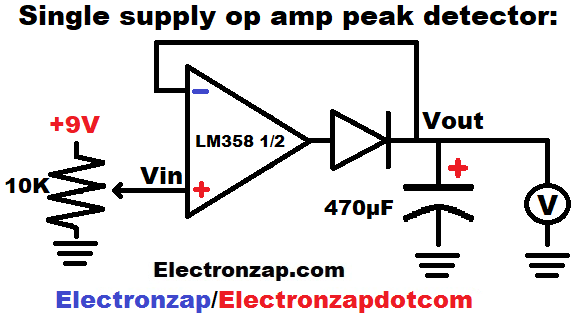
- As the trimpot voltage to the non inverting input (+) goes up, the output voltage will rise so that its applies the + voltage to the inverting (-) input.
- Actual output voltage will have to be about 0.6V higher than + input due to the approx. 0.6V diode drop between the output and – input.
- Capacitor will also charge to the voltage at the the + and – inputs.
- Lowering the voltage at the + input will lower the voltage at the output, but will not discharge the capacitor due to the rectifier diode being reverse biased.
- The capacitor will self discharge over time. Also, measuring it’s voltage or using it as a signal will help discharge the capacitor based on the resistance/impedance of what is measuring the voltage. But, it should stay close to the voltage that it was charged to for a while.
- For a more practical circuit, some kind of switch should be added parallel to the capacitor and some resistance should be added between the output and the diode. That way you can short circuit discharge the capacitor after you are done with the stored voltage, and there won’t be high current from the output when you do so.
Video:
To support this site, check out the following links:
- Become a Patron!
- Check out my YouTube videos! https://www.youtube.com/c/Electronzap/videos
- Products I used in my videos or otherwise think look like a good buy. As an Amazon associate, I earn from qualifying purchases. https://www.amazon.com/shop/electronzapdotcom
This is a new page that will be updated soon!
- Information on this site is not guaranteed to be accurate. Always consult the manufacturer info/datasheet of parts you use. Research the proper safety precautions for everything you do.
- Electronzap is a participant in the Amazon Services LLC Associates Program, an affiliate advertising program designed to provide a means for sites to earn advertising fees by advertising and linking to amazon.com.