Table of Contents
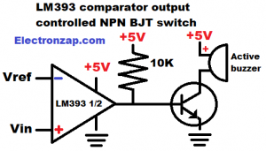
LM393 comparator has an open collector output. It does not provide power while the output is high. Instead, it is like a switch that is turned off while high. There needs to be a pull up resistor in order to provide positive voltage to any load.
- A reference voltage is placed at the inverting (-) input.
- A signal voltage is applied to the non inverting (+) input.
- If + input voltage is higher than – input voltage, then the output is high. The IC output is basically off, but the pull up resistor will turn the NPN Bipolar Junction Transistor (BJT) transistor on. The active buzzer will have practically all of the supply voltage across it, and it will buzz.
- If + input voltage is lower than – input, then the output is low. It is connected to ground, and all of the current through the pull up resistor will be sunk to ground. The transistor will have 0V at both it’s base and emitter, so no current flows through it. Therefore there is also no collector to emitter current. The transistor is off, and the buzzer will make no noise, as no current can flow through it.
Brief Circuit Schematics with Short Video List of Pages
Video:
To support this site, check out the following links:
- Become a Patron!
- Check out my YouTube videos! https://www.youtube.com/c/Electronzap/videos
- Products I used in my videos or otherwise think look like a good buy. As an Amazon associate, I earn from qualifying purchases. https://www.amazon.com/shop/electronzapdotcom
This is a new page that will be updated soon!
- Information on this site is not guaranteed to be accurate. Always consult the manufacturer info/datasheet of parts you use. Research the proper safety precautions for everything you do.
- Electronzap is a participant in the Amazon Services LLC Associates Program, an affiliate advertising program designed to provide a means for sites to earn advertising fees by advertising and linking to amazon.com.