Table of Contents
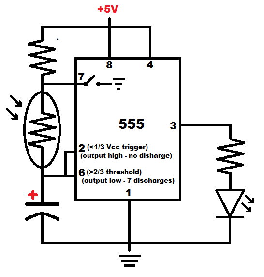
Putting the LDR between 555 timer pin 7 and the tied together pins 2 and 6, will make it so that the LDR is what primarily sets both the high and low output timing based on light level. That is, as long as the +5V to pin 7 resistor is of relatively low value.
Remember that pin 7 connects to ground internally while the output is low. Therefore you need to make sure that the current flowing through pin 7 isn’t too high. It needs to sink the current through the resistor from the +5V supply voltage, plus the current from the capacitor when there’s a lot of light on the LDR.
LDRs typically have very low resistance under bright light.
Video:
To support this site, check out the following links:
- Become a Patron!
- Check out my YouTube videos! https://www.youtube.com/c/Electronzap/videos
- Products I used in my videos or otherwise think look like a good buy. As an Amazon associate, I earn from qualifying purchases. https://www.amazon.com/shop/electronzapdotcom
- Information on this site is not guaranteed to be accurate. Always consult the manufacturer info/datasheet of parts you use. Research the proper safety precautions for everything you do.
- Electronzap is a participant in the Amazon Services LLC Associates Program, an affiliate advertising program designed to provide a means for sites to earn advertising fees by advertising and linking to amazon.com.